Kia Optima DL3: Seat Electrical / Walk-in Switch
Components and components location
| Component Location |
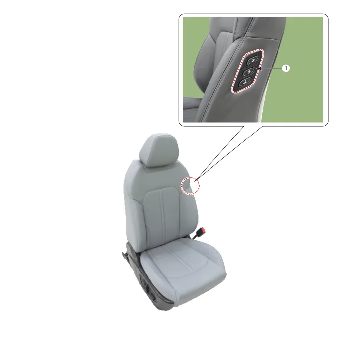
| 1. Walk-in switch |
Repair procedures
| Removal |
When prying with a flat-tip screwdriver or use a prying trim tool, wrap it with protective tape, and apply protective tape around the related parts, to prevent damage. |

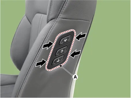
| 1. |
Remove the walk-in switch (A) by pressing the hooks.
|
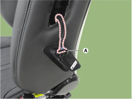
| 2. |
Disconnect the walk-in switch connector (A).
|
| Installation |
| 1. |
Install in the reverse order of removal. |
Components and components location Components 1. Lumbar support motor 2. Reclining motor 3. Front height motor 4.
Components and components location Component Location 1. Relaxion comfort switch 2. Walk-in switch 3. Relaxion comfort seat unit (RCSU) Schematic diagrams Connector and Terminal Function Pin Function Connector A Connector B 1 Battery (+) Slide motor switch (Forward) 2 Slide motor (Forward) Slide motor switch (Backward) 3 Slide motor (Backward) Relaxion comfort switch (Forward) 4 Recline motor (Forward) Relaxion comfort switch (Backward) 5 Recline motor (Backward) Rear height motor switch (Up) 6 Ground Rear height motor switch (Down) 7 Battery (+) Relaxion comfort switch 8 - Return switch 9 Rear height motor (Up) - 10 Rear height motor (Down) - 11 - Sensor power 12 Ground IGN2 13 IGN1 14 ECU (Battery +) 15 Walk-in switch Slide (Forward) 16 Walk-in switch Slide (Backward) 17 Walk-in switch Recline (Forward) 18 Walk-in switch Recline (Backward) 19 Walk-in relaxion comfort switch 20 Walk-in return switch 21 ECU (Ground) 22 - 23 - 24 Limit set power 25 Slide motor sensor 26 Recline motor sensor 27 Rear height motor sensor 28 Virtual limit set switch Repair procedures Removal Walk-in Switch 1.
Other information:
Kia Optima DL3 2019-2026 Service and Repair Manual: Panorama Sunroof Switch
Schematic diagrams Connector and Terminal Function Repair procedures Inspection 1. Remove the overhead console lamp. (Refer to Lighting System - "Overhead Console Lamp") 2. Check for continuity between the terminals in each switch position according to the table
Kia Optima DL3 2019-2026 Service and Repair Manual: Heater & A/C Control Unit (Manual)
Components and components location Components Connector Pin Function [Connector A] Pin NO Funtion Pin NO Funtion 1 Battery (+) 21 IGN2 2 ILL+ (TAIL) 22 IGN1
Categories
- Manuals Home
- Kia Optima Owners Manual
- Kia Optima Service Manual
- Driving your vehicle
- Brake System
- Charging System
- New on site
- Most important about car
