Kia Optima DL3: Evaporative Emission Control System / Purge Control Solenoid Valve (PCSV)
Specifications
| Specification |
|
Item |
Specification |
|
Coil Resistance (Ω) |
22.0 - 26.0 [20°C (68°F)] |
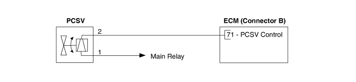
Schematic diagrams
| Circuit Diagram |
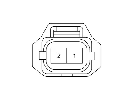
Harness Connector
Repair procedures
| Inspection |
| 1. |
Turn the ignition switch OFF. |
| 2. |
Disconnect the PCSV connector. |
| 3. |
Measure resistance between the PCSV terminals 1 and 2. |
| 4. |
Check that the resistance is within the specification.
|
| Removal |
| 1. |
Disconnect the negative battery (-) terminal. |
| 2. |
Remove the air cleaner. (Refer to Engine Mechanical System - "Air Cleaner") |
| 3. |
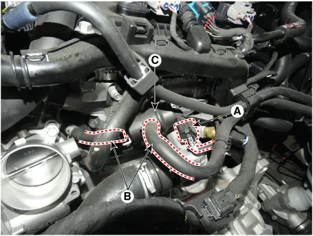
Disconnect the purge control solenoid valve connector (A). |
| 4. |
Disconnect the vapor hoses (B) from the purge control solenoid valve. |
| 5. |
Remove the valve (C) from the surge tank after pulling it.
|
| Installation |
| 1. |
Install in the reverse order of removal.
|

Repair procedures Removal 1. Disconnect the negative battery (-) terminal. 2. Remove the [LH] rear wheel guard.
Description and operation Description Exhaust emissions (CO, HC, NOx) are controlled by a combination of engine modifications and the addition of special control components.
Other information:
Kia Optima DL3 2019-2026 Service and Repair Manual: Panorama Sunroof
C
Kia Optima DL3 2019-2026 Service and Repair Manual: Relaxion Comfort Seat
Components and components location Component Location 1. Relaxion comfort switch 2. Walk-in switch 3. Relaxion comfort seat unit (RCSU) Schematic diagrams Connector and Terminal Function Pin Function Connector A Co
Categories
- Manuals Home
- Kia Optima Owners Manual
- Kia Optima Service Manual
- Emergency trunk safety release
- Timing Chain
- Restraint
- New on site
- Most important about car
