Kia Optima DL3: Emission Control System
Service data
| Specifications |
Purge Control Solenoid Valve (PCSV)
▷ Specification
|
Item |
Specification |
|
Coil Resistance (Ω) |
22.0 - 26.0 [20°C (68°F)] |
Tightening torque
| Tightening Torques |
|
Item |
kgf.m |
N.m |
lb-ft |
|
Positive Crankcase Ventilation (PCV) Valve |
0.2 - 0.3 |
1.96 - 2.94 |
1.45 - 2.17 |
Description and operation
| Description |
Emissions Control System consists of three major systems.
| • |
Crankcase Emission Control System prevents blow-by gas from releasing into the atmosphere. This system recycles gas back into the intake manifold (Closed Crankcase Ventilation Type). |
| • |
Evaporative Emission Control System prevents evaporative gas from releasing into the atmosphere. This system burns gas at appropriate engine operating condition after gathering it in the canister. |
| • |
Exhaust Emission Control System converts the three pollutants [hydrocarbons (HC), carbon monoxide (CO), and oxides of nitrogen (NOx)] into harmless substances by using the 3-way catalytic converter. |
Troubleshooting
| Troubleshooting |
|
Symptom |
Suspect Area |
|
Engine will not start or stuggle to start |
Vapor hose damaged or disconnected |
|
Engine stuggle to start |
Malfunction of the Purge Control Solenoid Valve |
|
Rough idle or engine stalls |
Vapor hose damaged or disconnected |
|
Malfunction of the PCV valve |
|
|
Rough idle |
Malfunction of the Evaporative Emission Control System |
|
Excessive oil consumption |
Positive crankcase ventilation line clogged |
Schematic diagrams
| Schematic Diagram |
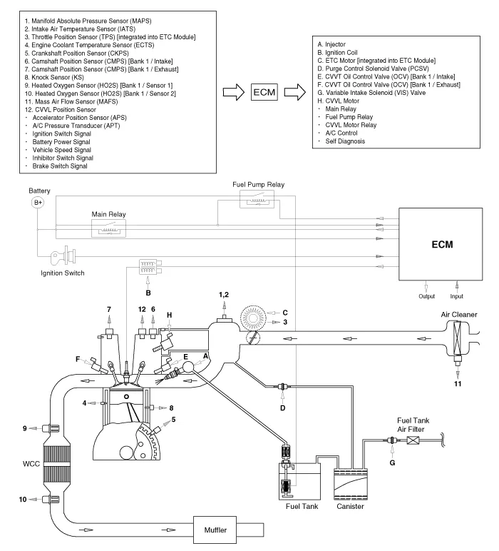
Components and components location
| Components Location |
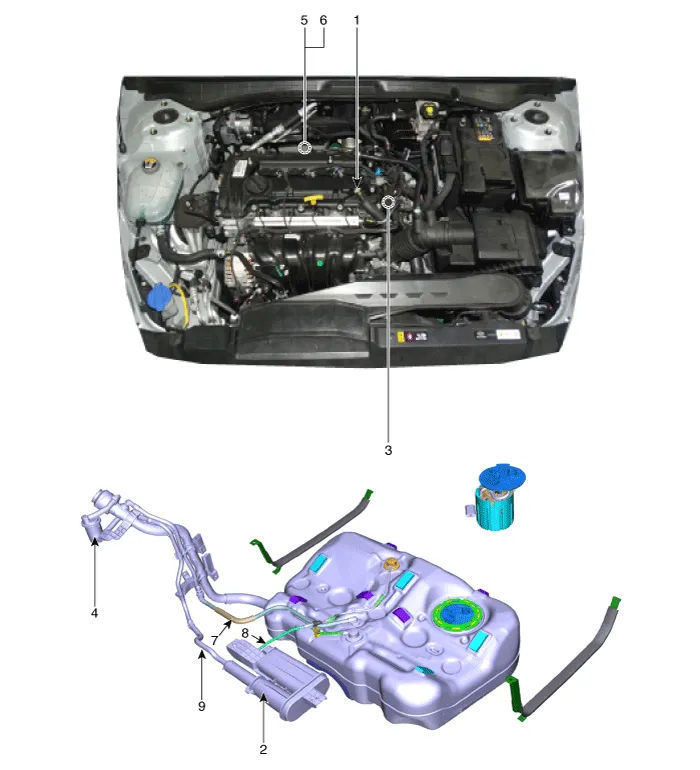
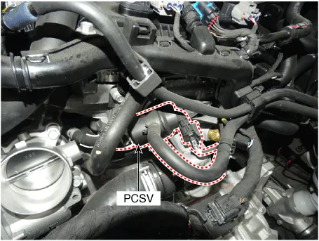
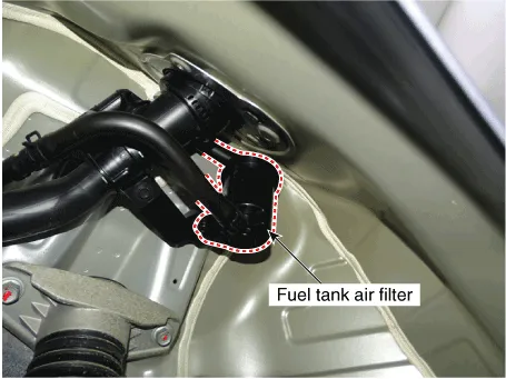
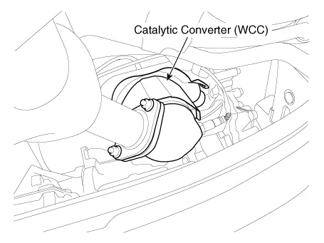
| 1. PCV valve 2. Canister 3. Purge control solenoid valve (PCSV) 4. Fuel Tank Air Filter 5. Catalytic converter (WCC) |
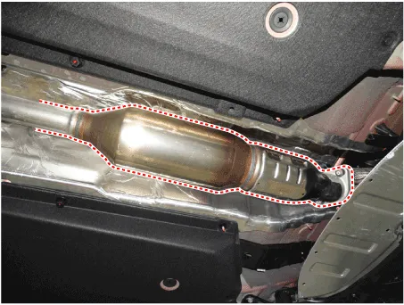
6. Catalytic converter (UCC)
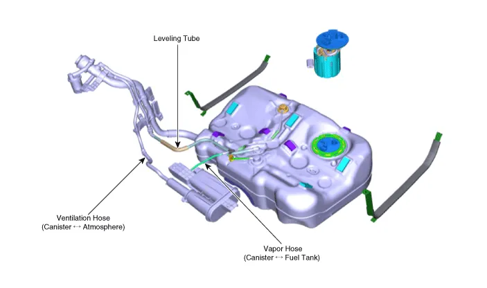
7. Leveling Tube 8. Vapor Hose (Canister ↔ Fuel Tank) 9. Ventilation Hose (Canister ↔ Atmosphere) |
|
1. PCV valve |
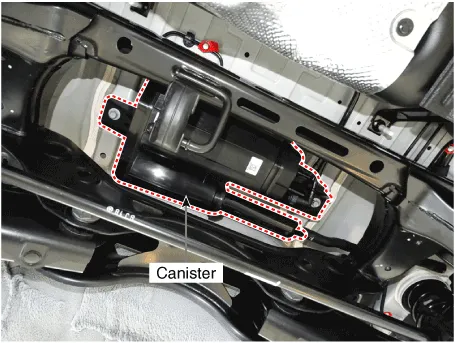
2. Canister |
|
|
|
|
3. Purge control solenoid valve (PCSV) |
4. Fuel Tank Air Filter |
|
|
|
|
5. Catalytic converter (WCC) |
6. Catalytic converter (UCC) |
|
|
|
|
7. Leveling Tube 8. Vapor Hose (Canister ↔ Fuel Tank) 9. Ventilation Hose (Canister ↔ Atmosphere) |
|
|
|
|
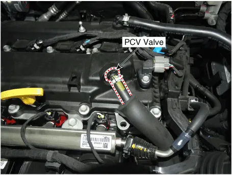
Repair procedures Inspection 1. Disconnect the negative battery (-) terminal. 2. Remove the fuse box cover.
Schematic diagrams Schematic Diagram Repair procedures Inspection 1. After disconnecting the vapor hose from the PCV valve, remove the PCV valve.
Other information:
Kia Optima DL3 2019-2026 Service and Repair Manual: Rear Glass Defogger Printed Heater
Repair procedures Inspection • Wrap tin foil around the end of the voltmeter test lead to prevent damaging the heater line. Apply pressure on the tin foil with hand and move the tin foil along the grid line to check for open circ
Kia Optima DL3 2019-2026 Service and Repair Manual: Smart Key Unit
Schematic diagrams Connector and Terminal Function Pin Function Connector A Connector B Connector C Connector D 1 - Front washer switch (Output) - Driver outside handle switch (Input)
Categories
- Manuals Home
- Kia Optima Owners Manual
- Kia Optima Service Manual
- Brake System
- Heating, Ventilation and Air Conditioning
- Engine Control Module (ECM)
- New on site
- Most important about car
