Kia Optima DL3: Rear Suspension System / Rear Lower Arm
Repair procedures
| Removal |
| 1. |
Disconnect the (-) battery terminal. |
| 2. |
Remove the rear wheel and tire. (Refer to Tires/Wheels - "Wheel") |
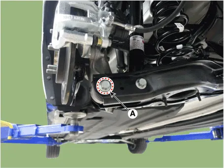
| 3. |
Loosen the bolt and nut (A) and then remove the rear lower arm from the rear axle.
|

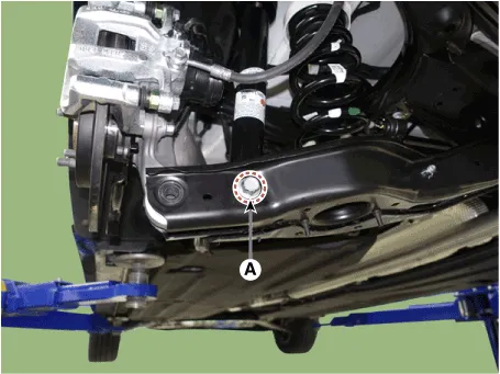
| 4. |
Loosen the bolt and nut (A) and remove the rear shock absorber from the rear lower arm.
|
| 5. |
Loosen the bolt and nut (A) and then disconnect the rear stabilizer link from the rear lower arm.
|
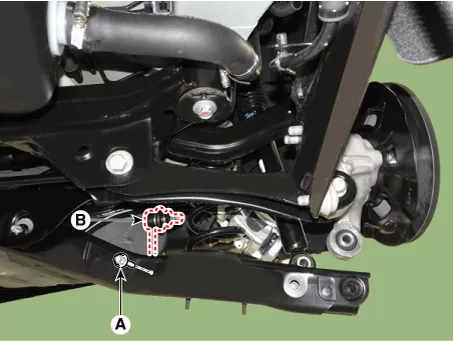
| 6. |
Remove the rear coil spring (A).
|
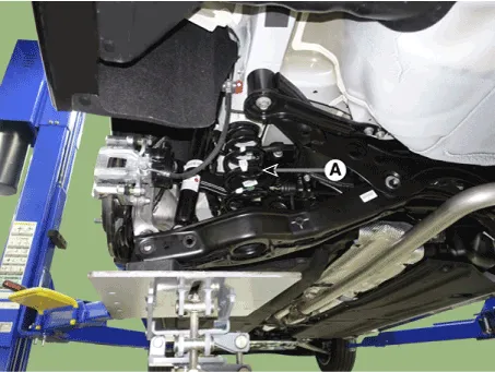
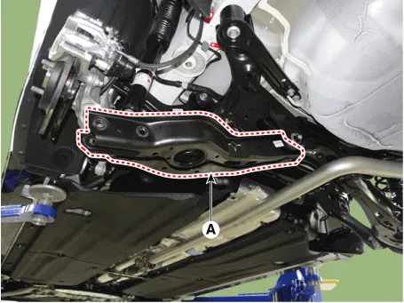
| 7. |
Loosen the bolt and nut and then remove the rear lower arm (A).
|
| Inspection |
| 1. |
Check the bushing for wear and deterioration. |
| 2. |
Check the rear lower arm for deformation. |
| 3. |
Check the coil spring and spring pad for deterioration and deformation. |
| 4. |
Check for all bolts and nut. |
| Installation |
| 1. |
Install in the reverse order of removal. |
| 2. |
Check the alignment. (Refer to Suspension System - "Alingment") |
Repair procedures Removal 1. Disconnect the (-) battery terminal. 2. Remove the rear wheel and tire.
Repair procedures Removal 1. Disconnect the (-) battery terminal. 2. Remove the rear wheel and tire.
Other information:
Kia Optima DL3 2019-2026 Service and Repair Manual: Panorama Sunroof Motor
Schematic diagrams Connector and Terminal Function Repair procedures Inspection 1. Disconnect the negative battery terminal. 2. Remove the rear pillar trim [LH]. (Refer to Body - "Rear Pillar Trim") 3.
Kia Optima DL3 2019-2026 Service and Repair Manual: Heater & A/C Control Unit (Manual)
Components and components location Components Connector Pin Function [Connector A] Pin NO Funtion Pin NO Funtion 1 Battery (+) 21 IGN2 2 ILL+ (TAIL) 22 IGN1
Categories
- Manuals Home
- Kia Optima Owners Manual
- Kia Optima Service Manual
- Engine Control / Fuel System
- Engine Mechanical System
- Battery
- New on site
- Most important about car
