
Kia Optima DL3: Lighting System / Room Lamp
Repair procedures
| Removal |
When removing with a flat-tip screwdriver or remover, wrap protective tape around the tools to prevent damage to components. |

| 1. |
Disconnect the negative battery terminal. |
| 2. |
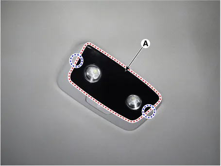
Remove the room lamp lens (A) by using a flat-tip screwdriver or remover.
|
| 3. |
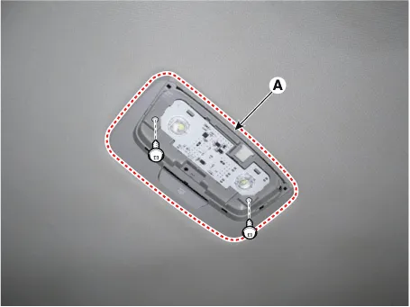
Remove the room lamp (A) by loosening the mounting screws.
|
| 4. |
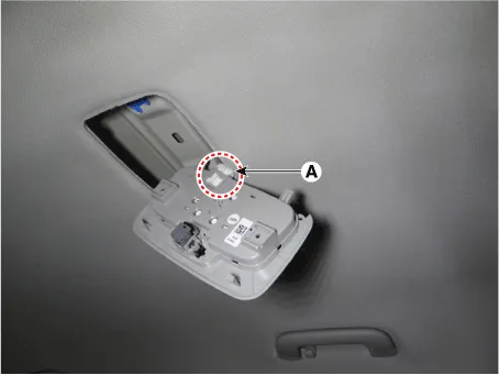
Disconnect the room lamp connector (A).
|
| 5. |
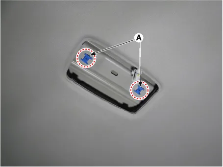
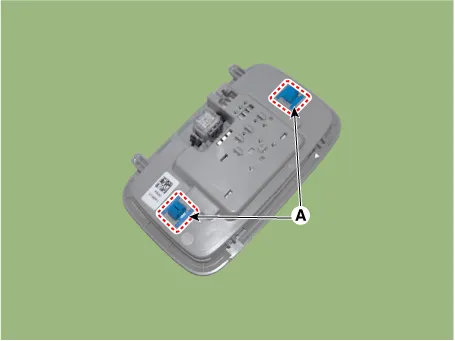
Remove the room lamp mounting clips (A).
|
| Installation |
| 1. |
Install in the reverse order of removal.
|

Schematic diagrams Connector and Terminal Function Repair procedures Removal 1. Disconnect the negative battery terminal.
Repair procedures Removal When removing with a flat-tip screwdriver or remover, wrap protective tape around the tools to prevent damage to components.
Other information:
Kia Optima DL3 2019-2026 Service and Repair Manual: Hazard Lamp Switch
Schematic diagrams Connector and Terminal Function Repair procedures Removal 1. Disconnect the negative battery terminal. 2. Remove the crash pad garnish [RH]. (Refer to Body - "Crash Pad Garnish") 3.
Kia Optima DL3 2019-2026 Service and Repair Manual: Ambient Temperature Sensor
Description and operation Description The ambient temperature sensor is located at the front of the condenser and detects ambient air temperature. It is a negative type thermistor; resistance will increase with lower temperature, and decrease with higher temperature.
Categories
- Manuals Home
- Kia Optima Owners Manual
- Kia Optima Service Manual
- Brake System
- Timing Chain
- Instrument panel overview
- New on site
- Most important about car
