Kia Optima DL3: Lighting System / Vanity Lamp
Repair procedures
| Removal |
When removing with a flat-tip screwdriver or remover, wrap protective tape around the tools to prevent damage to components. |

| 1. |
Disconnect the negative battery terminal. |
| 2. |
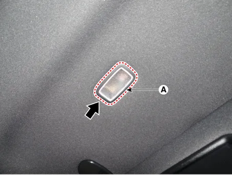
Remove the vanity lamp (A) by using a flat-tip screwdriver or remover.
|
| 3. |
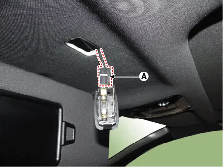
Disconnect the connector (A) from the vanity lamp.
|
| Installation |
| 1. |
Install in the reverse order of removal. |
| Replacement |
When removing with a flat-tip screwdriver or remover, wrap protective tape around the tools to prevent damage to components. |
| 1. |
Disconnect the negative battery terminal. |
| 2. |
Remove the vanity lamp (A) by using a flat-tip screwdriver or remover.
|
| 3. |
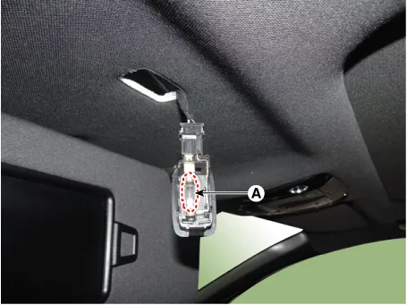
Replace the vanity lamp bulb (A).
|
Repair procedures Removal When removing with a flat-tip screwdriver or remover, wrap protective tape around the tools to prevent damage to components.
Repair procedures Removal When removing with a flat-tip screwdriver or remover, wrap protective tape around the tools to prevent damage to components.
Other information:
Kia Optima DL3 2019-2026 Service and Repair Manual: Mood Lamp Unit
Schematic diagrams Connector and Terminal function Repair procedures Removal When removing with a flat-tip screwdriver or remover, wrap protective tape around the tools to prevent damage to components.
Kia Optima DL3 2019-2026 Service and Repair Manual: Ventilated and Heated Seat Switch
Schematic diagrams Connector and Terminal Function [Front Seat] [Ventilation+Heater Type / Non-Heater Type] Pin Function Pin Function Ventilation+Heater Type Non-Heater Type Ventilation+Heater Type Non-Heater Type
Categories
- Manuals Home
- Kia Optima Owners Manual
- Kia Optima Service Manual
- Emergency trunk safety release
- Air bag collision sensors
- Battery
- New on site
- Most important about car
