
Kia Optima DL3: Cylinder Block / Rear Oil Seal
Components and components location
| Components |

| 1. Rear Oil Seal |
Repair procedures
| Replacement |
| 1. |
Remove the automatic transaxle. (Refer to Automatic Transaxle System - "Automatic Transaxle") |
| 2. |
Remove the drive plate. (Refer to Cylinder Block – “Drive Plate”) |
| 3. |
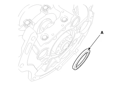
Remove the rear oil seal (A).
|
| 4. |
Install a new rear oil seal.
|

| 5. |
Install the other parts reverse order of removal. |
Components and components location Components 1. Adapter plate 2. Drive plate Repair procedures Removal and Installation 1.
Components and components location Components 1. Piston ring 2. Snap ring 3. Piston pin 4. Piston 5. Connecting rod 6.
Other information:
Kia Optima DL3 2019-2026 Service and Repair Manual: Power Door Mirror Switch
Schematic diagrams Connector and Terminal Function Pin Function 1 B-CAN (Low) 2 B-CAN (High) 3 Ground (Assist safety) 4 Assist safety 5 LIN (For IMS)
Kia Optima DL3 2019-2026 Service and Repair Manual: Rear Glass Defogger Printed Heater
Repair procedures Inspection • Wrap tin foil around the end of the voltmeter test lead to prevent damaging the heater line. Apply pressure on the tin foil with hand and move the tin foil along the grid line to check for open circ
Categories
- Manuals Home
- Kia Optima Owners Manual
- Kia Optima Service Manual
- Headlamps
- Suspension System
- Lift And Support Points
- New on site
- Most important about car
