Kia Optima DL3: Hydraulic System / 26 Brake Control Solenoid Valve (26/B_VFS)
Specifications
Item
|
Specification
|
Control type
|
N/L (Normal Low)
|
Control pressure (kpa (kgf/cm², psi))
|
0 - 1,569.06 (0 - 16, 0 - 227.57)
|
Current (mA)
|
0 - 1,100
|
Coil resistance (Ω)
|
5.3 ± 0.3
|
Description and operation
| • |
26 Brake control solenoid valve is a Variable Force Solenoid (VFS) type.
|
| • |
When TCM supplies variable current to solenoid valve, hydraulic pressure
of 26 brake is controlled by solenoid valve.
|
26 Brake control solenoid
valve operation table
|
26/B_VFS
|
N/L
|
N, P
|
|
1
|
|
2
|
●
|
3
|
|
4
|
|
5
|
|
6
|
●
|
R
|
|
● : Connected status
Components and components location
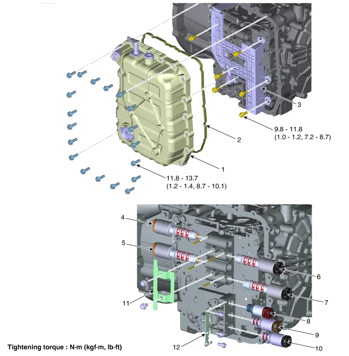
1. Valve Body Cover
|
8. SS-A ON/OFF Solenoid Valve
|
2. Valve Body Gasket
|
9. Torque Converter Control Solenoid
Valve
|
3. Main Harness
|
10. Line Pressure Control Solenoid
Valve
|
4. 26 Brake Control Solenoid
Valve
|
11. Support Bracket
|
5. 35R Clutch Control Solenoid
Valve
|
12. Support Bracket
|
6. Underdrive Brake Control Solenoid
Valve
|
|
7. Overdrive Clutch Control Solenoid
Valve
|
|
Repair procedures
| 1. |
The automatic transaxle system can be more quickly diagnosed for troubles
by using the vehicle diagnostic system (KDS).
KDS provides the following information.
| (1) |
Self diagnosis : Inspects and displays diagnostic trouble code
(DTC)
|
| (2) |
Sensor data : Checks the system input/output value status
|
| (3) |
Forced operation : Checks the system operating status
|
| (4) |
Additional function : Controls system options, zero point adjustment
and other functions
|
|
| 1. |
Switch "OFF" ignition.
|
| 2. |
Remove the air cleaner assembly.
(Refer to Engine Mechanical System - "Air cleaner")
|
| 3. |
Remove the battery and battery tray.
(Refer to Engine Electrical System - "Battery")
|
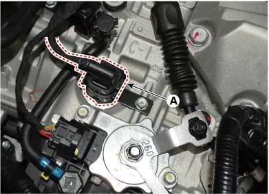
| 4. |
Disconnect the solenoid valve connector (A).
|
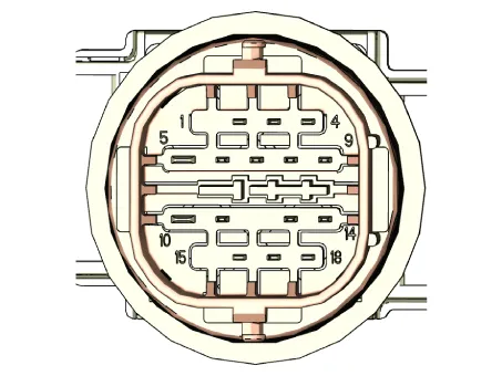
| 5. |
Measure the resistance between power terminal (5) and signal terminal
(11).
|
Specification : 5.3 ± 0.3 Ω
|
|
| • |
Automatic transaxle is composed of delicate components. Be careful
not to cause any damage on the component in the course of assembly
and disassembly.
|
| • |
Maintain clean condition so that foreign substance does not get
into the automatic transaxle.
|
| • |
Use a coated apron, latex gloves, and stainless tray to prevent
foreign substance from getting into the transaxle.
|
|
| 1. |
Remove the under cover.
(Refer to Engine Mechanical System - "Engine Room Under Cover")
|
| 2. |
Remove the ATF drain plug (A), allow the fluid to drain out and then
reinstall the drain plug.
|
Tightening torque:
33.3 - 43.1 N·m (3.4 - 4.4 kgf·m, 24.6 - 31.8 lb·ft)
|
| •
|
The existing ATF drain plug gasket must be replaced with
a new one. (Do not reuse it.
|
| •
|
Automatic transaxle fluid (ATF) can be reused. Collect
it using a clean 10-liter beaker.
|
|
|
| 3. |
Remove the air duct and air cleaner assembly.
(Refer to Engine Mechanical System - "Air cleaner")
|
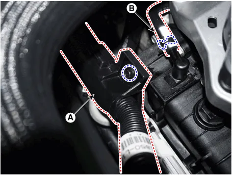
| 4. |
Remove the fixing clip (A) and the air breather hose (B).
|
Tightening torque:
9.8 - 11.8 N·m (1.0 - 1.2 kgf·m, 7.2 - 8.7 lb·ft)
|
|
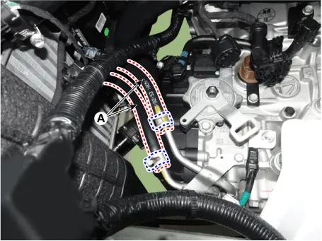
| 5. |
Separate the ATF cooler hose (A).
|
| 6. |
Lift the vehicle after loosening valve body cover upper bolts.
|
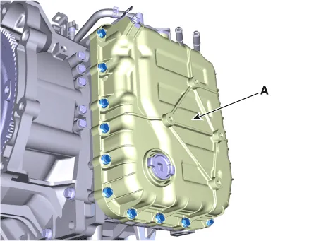
| 7. |
Remove the valve body cover (A) by loosening bolts.
|
Tightening torque:
11.8 - 13.7 N·m (1.2 - 1.4 kgf·m, 8.7 - 10.1 lb·ft)
|
|
| 8. |
Remove the main harness (A) after removing the bolts.
|
Tightening torque:
9.8 - 11.8 N·m (1.0 - 1.2 kgf·m, 7.2 - 8.7 lb·ft)
|
|
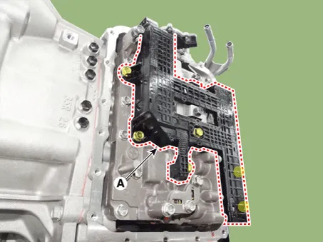
| 9. |
Remove solenoid valve support bracket (A) after loosening the bolts.
|
Tightening torque:
9.8 - 11.8 N·m (1.0 - 1.2 kgf·m, 7.2 - 8.7 lb·ft)
|
|
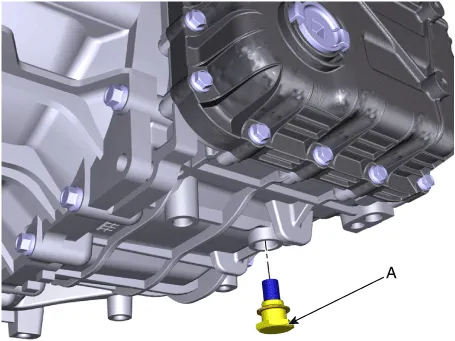
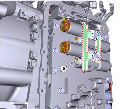
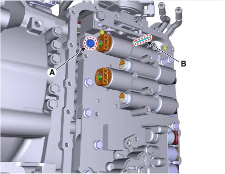
| 10. |
Remove the solenoid valve fixing pin (B) and loosen the valve body mounting
bolt (A).
|
Tightening torque:
9.8 - 11.8 N·m (1.0 - 1.2 kgf·m, 7.2 - 8.7 lb·ft)
|
|
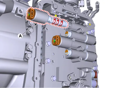
| 11. |
Remove the 26 brake control solenoid valve (A).
|
| 1. |
Install in the reverse order of removal.
| •
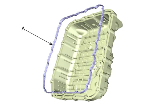
|
The existing valve body cover gasket (A) must be replaced
with a new one. (Do not reuse it.)
|
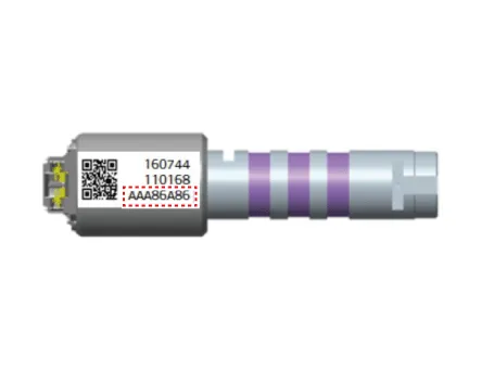
| •
|
Check the code (oil pressure characteristics value) at
the first before installing the solenoid valve.
|
|
|
| 2. |
Perform the procedures below after installing.
| (1) |
Refill the automatic transaxle with fluid.
(Refer to Hydraulic System - "Fluid")
|
| (2) |
Clear the diagnostic trouble codes (DTC) using the KDS. Disconnecting
the battery negative terminal will not clear the DTCs. Clear DTCs
using the KDS at all times.
|
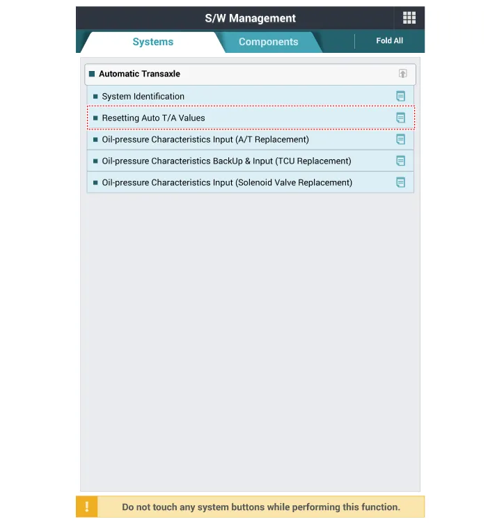
| (3) |
Reset the automatic transaxle adaptive values using the KDS.
|
| (4) |
Perform the oil pressure characteristics input procedure using
the KDS.
(Refer to Hydraulic System - "Oil pressure characteristics input")
|
| (5) |
Check for leakage of coolant or fluid from hose connection during
engine start.
|
| (6) |
Perform the TCM adaptive values learning procedure.
(Refer to Automatic Transaxle Control System - "Adjustment")
|
|
Specifications
Specification
Item
Specification
Control type
N/L (Normal Low)
Control pressure (kpa (kgf/cm², psi))
0 - 1,569.
Specifications
Specification
Item
Specification
Control type
N/H (Normal High)
Control pressure (kpa (kgf/cm², psi))
0 - 1,569.
Other information:
Specifications
Specifications
Item
Specifications
Rated voltage
DC 12 V
Operating voltage
DC 9 - 16 V
Operating temperature range
-22 to 167°F (-30 to 75°C)
Dark current
Max.
Repair procedures
Inspection
When prying with a flat-tip screwdriver or use a prying trim tool, wrap
it with protective tape, and apply protective tape around the related parts,
to prevent damage.

