Kia Optima DL3: Seat Electrical / Ventilated and Heated Seat
Schematic diagrams
| Connector and Terminal Function |

|
Pin |
Function |
|
|
Connector A |
Connector B |
|
|
1 |
Driver heater ground (-) |
Driver blower speed (+) |
|
2 |
Passenger heater ground (-) |
- |
|
3 |
Driver cushion heater power (+) |
CAN (Low) |
|
4 |
Driver back heater power (+) |
CAN (High) |
|
5 |
Passenger cushion heater power (+) |
- |
|
6 |
Passenger back heater power (+) |
LIN |
|
7 |
ECU (Ground) |
Detent |
|
8 |
ECU (Ground) |
IGN1 |
|
9 |
|
Driver blower speed |
|
10 |
Passenger blower speed |
|
|
11 |
Illumination (-) |
|
|
12 |
Driver NTC (-) |
|
|
13 |
Passenger NTC (-) |
|
|
14 |
- |
|
|
15 |
- |
|
|
16 |
- |
|
|
17 |
- |
|
|
18 |
- |
|
|
19 |
- |
|
|
20 |
IGN2 |
|
|
21 |
- |
|
|
22 |
Driver NTC (+) |
|
|
23 |
Passenger NTC (+) |
|
|
24 |
- |
|
Repair procedures
| Removal |
Ventilation Seat Unit
| 1. |
Remove the heater unit. (Refer to Seat Electrical - "Heated Seats Only") |
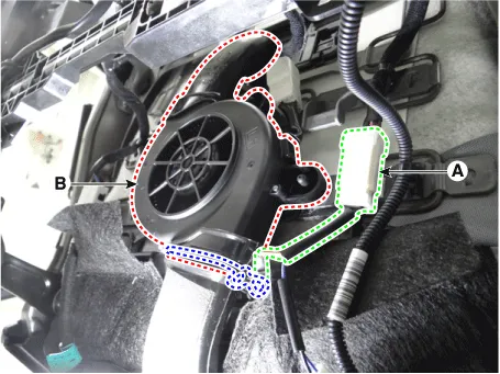
Ventilation Seat Blower
| 1. |
Disconnect the negative battery terminal. |
| 2. |
Remove the front seat assembly. (Refer to Body - "Front Seat Assembly") |
| 3. |
Disconnect the ventilation seat blower connector (A). |
| 4. |
Remove the ventilation seat blower (B) by removing the clips.
|
| Installation |
| 1. |
Install in the reverse order of removal. |
Schematic diagrams Connector and Terminal Function [Front Seat] [Ventilation+Heater Type / Non-Heater Type] Pin Function Pin Function Ventilation+Heater Type Non-Heater Type Ventilation+Heater Type Non-Heater Type 1 IGN1 - 9 Illumination (+) 2 - - 10 - 3 - - 11 Illumination (-) 4 Ground - 12 - 5 - 13 Steering heater mode - 6 - 14 Steering heater indicator - 7 LIN - 15 Driver mode switch (CW) 8 Ground 16 Driver mode switch (CCW) [Heater Type] Pin Function Pin Function 1 Heater indicator (High)_RH 13 Heater mode_RH 2 Heater indicator (Mid)_RH 14 - 3 Heater indicator (Low)_RH 15 - 4 - 16 Ground 5 Driver mode switch (CW) 17 - 6 Driver mode switch (CCW) 18 Illumination (-) 7 Steering heater mode 19 - 8 Steering heater indicator 20 Illumination (+) 9 Heater mode_LH 21 - 10 Heater indicator (High)_LH 22 - 11 Heater indicator (Mid)_LH 23 - 12 Heater indicator (Low)_LH 24 - [Rear Seat] [Safety Type] Pin Function Pin Function 1 Ground (Illumination -) 5 Ground 2 Door lock switch 6 Door lock indicator 3 Door unlock switch 7 Safety power window 4 Battery + (Illumination +) 8 - [Manual Type] Pin Function Pin Function 1 Ground 7 Driver window down 2 Seat warmer (High) 8 Window enble 3 Window down motor 9 Ground (Illumination -) 4 Seat warmer (Low) 10 Driver window up 5 Window up motor 11 Battery + (Illumination +) 6 Seat warmer switch 12 Battery (+) Repair procedures Inspection [Front Seat] 1.
Repair procedures Inspection 1. Remove the front seat back. (Refer to Body - "Front Seat Back Cover") 2.
Other information:
Kia Optima DL3 2019-2026 Service and Repair Manual: Rear Glass Defogger Switch
Repair procedures Inspection 1. In the body electrical system, failure can be quickly diagnosed by using the vehicle diagnostic system (KDS). The diagnostic system (KDS) provides the following information. (1) Self diagnosis : Checking failure and code number (DTC).
Kia Optima DL3 2019-2026 Service and Repair Manual: Heater Core
Repair procedures Replacement 1. Disconnect the negative (-) battery terminal. 2. Remove the heater and blower assembly. (Refer to Heater - "Heater Unit") 3. Loosen the mounting screws and remove the heater core cover (A).
Categories
- Manuals Home
- Kia Optima Owners Manual
- Kia Optima Service Manual
- Automatic Transaxle System
- Timing Chain
- Lift And Support Points
- New on site
- Most important about car
