Kia Optima DL3: Seat Electrical / Lumbar Support System
Repair procedures
| Inspection |
| 1. |
Remove the front seat back. (Refer to Body - "Front Seat Back Cover") |
| 2. |
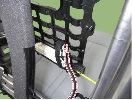
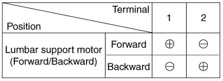
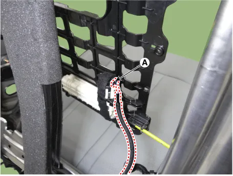
Disconnect the connector (A).
|
| 3. |
When the battery power is supplied to the motor connector, check the motor for smooth operation.
|
| Removal |
| 1. |
Remove the front seat back. (Refer to Body - "Front Seat Back Cover") |
| 2. |
Disconnect the connector (A) from lumbar support motor.
|
| 3. |
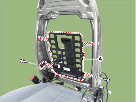
Remove the side airbag. (Refer to Restraint - "Side Airbag Module") |
| 4. |
Remove the lumbar support (A) after loosening the screws.
|
| Installation |
| 1. |
Install in the reverse order of removal. |
Schematic diagrams Connector and Terminal Function Pin Function Connector A Connector B 1 Driver heater ground (-) Driver blower speed (+) 2 Passenger heater ground (-) - 3 Driver cushion heater power (+) CAN (Low) 4 Driver back heater power (+) CAN (High) 5 Passenger cushion heater power (+) - 6 Passenger back heater power (+) LIN 7 ECU (Ground) Detent 8 ECU (Ground) IGN1 9 Driver blower speed 10 Passenger blower speed 11 Illumination (-) 12 Driver NTC (-) 13 Passenger NTC (-) 14 - 15 - 16 - 17 - 18 - 19 - 20 IGN2 21 - 22 Driver NTC (+) 23 Passenger NTC (+) 24 - Repair procedures Removal Ventilation Seat Unit 1.
Repair procedures Removal 1. Remove the front seat shield outer cover. (Refer to Body - "Front Seat Shield Outer Cover") 2.
Other information:
Kia Optima DL3 2019-2026 Service and Repair Manual: Power Door Locks
C
Kia Optima DL3 2019-2026 Service and Repair Manual: Power Window Motor
Schematic diagrams Circuit Diagram [Safety Window Motor] [Standard Window Motor] Repair procedures Inspection Front Power Window Motor 1. Disconnect the negative battery terminal. 2.
Categories
- Manuals Home
- Kia Optima Owners Manual
- Kia Optima Service Manual
- Automatic Transaxle System
- Charging System
- Brake System
- New on site
- Most important about car
