Kia Optima DL3: Charging System / Wireless Charging Indicator
Schematic diagrams
| Connector and Terminal function |

|
Pin |
Function |
|
1 |
Ground |
|
2 |
LED charging lamp (Green) |
|
3 |
LED charging lamp (Amber) |
|
4 |
- |
|
5 |
Illumination (-) |
|
6 |
Illumination (+) |
Repair procedures
| Removal |
| 1. |
Disconnect the negative battery terminal. |
| 2. |
Remove the console upper cover. (Refer to Body - "Floor Console Assembly") |
| 3. |
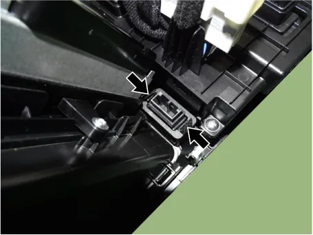
Disconnect the wireless power charger indicator connector (A).
|

| 4. |
Remove the wireless power charger indicator (A) by pressing the fixing hooks.
|

| Installation |
| 1. |
Install in the reverse order of removal. |
Specifications Specifications Items Specification Operating voltage DC 9 - 16 V Operating temperature -22 to 167 °F (-30 to +75 °C) Dark current MAX.
Description and operation Description The ECM (Electro Chromatic inside rear view Mirror) is one that automatically dims to protect the driver’s eyes when it senses light reflecting from the car behind.
Other information:
Kia Optima DL3 2019-2026 Service and Repair Manual: Smart Key System
Specifications Specifications Smart Key Unit Items Specification Rated voltage DC 12 V Operation voltage DC 9 - 16 V Operation temperature -40 to 185°F (-40 to 85°C) RF Receiver Items
Kia Optima DL3 2019-2026 Service and Repair Manual: Heating, Ventilation and Air Conditioning
Service data Service Data Air Conditioner ltem Specification Compressor Type 6SAS14 Oil type & Capacity ND-OIL 12 80 ± 10 cc (2.82 ± 0.
Categories
- Manuals Home
- Kia Optima Owners Manual
- Kia Optima Service Manual
- Brake System
- Floor Console Assembly
- Body Electrical System
- New on site
- Most important about car
