Kia Optima DL3: Audio/AVN System / Audio
Components and components location
| Components |
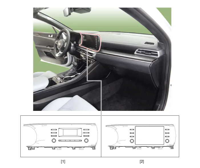
| 1. Audio head unit |
2. Display audio head unit
|
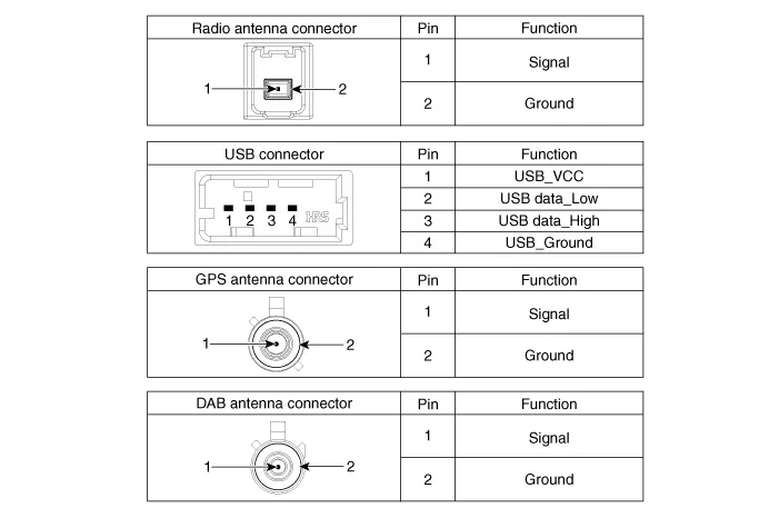
Schematic diagrams
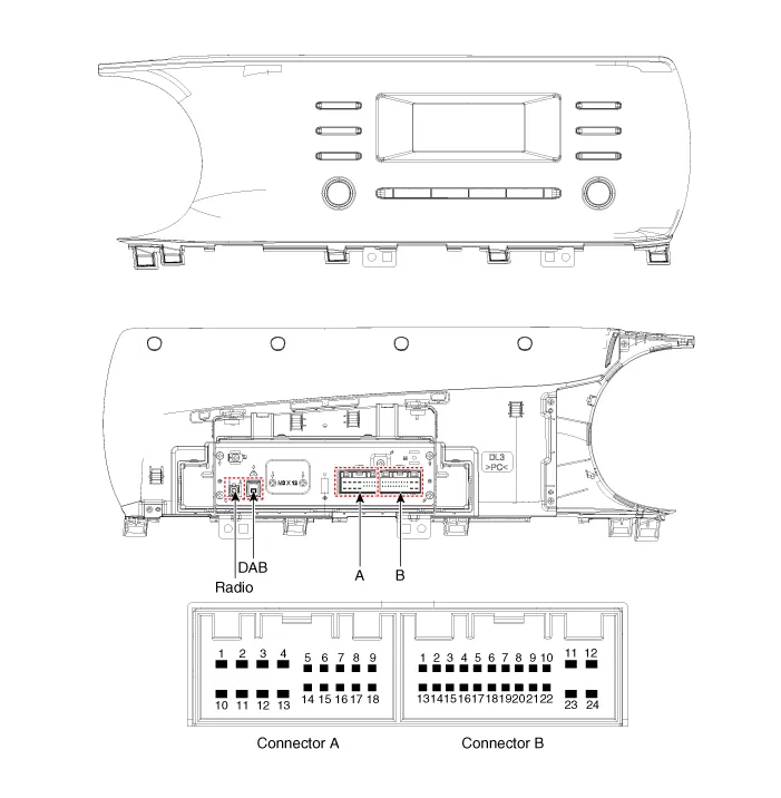
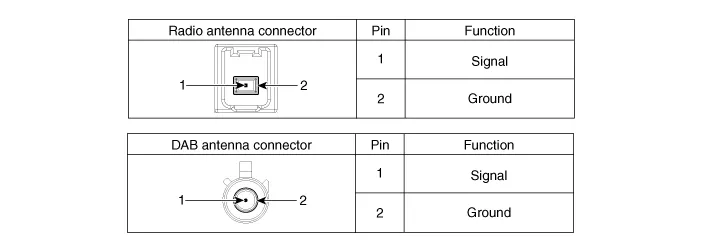
| Connector and Terminal Function |
Audio 4.0
|
Pin |
Function |
|
|
Connector A |
Connector B |
|
|
1 |
Left rear door speaker (+) |
- |
|
2 |
Left front door speaker (+) |
- |
|
3 |
Right front door speaker (+) |
- |
|
4 |
Right rear door speaker (+) |
Steering wheel key |
|
5 |
- |
- |
|
6 |
Door open |
USB data_High |
|
7 |
- |
USB_VCC |
|
8 |
Illumination (+) |
- |
|
9 |
Detent |
- |
|
10 |
Left rear door speaker (-) |
MIC (+) |
|
11 |
Left front door speaker (-) |
ACC |
|
12 |
Right front door speaker (-) |
Battery (+) |
|
13 |
Right rear door speaker (-) |
- |
|
14 |
- |
- |
|
15 |
- |
- |
|
16 |
- |
Vehicle speed signal |
|
17 |
Illumination (-) |
Steering wheel_key_Ground |
|
18 |
Antenna remote |
USB data_Low |
|
19 |
|
USB ground |
|
20 |
- |
|
|
21 |
- |
|
|
22 |
MIC (-) |
|
|
23 |
- |
|
|
24 |
Ground |
|
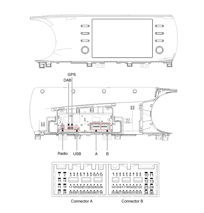
Display Audio 2.0
|
Pin |
Function |
|
|
Connector A |
Connector B |
|
|
1 |
Left rear door speaker (+) |
- |
|
2 |
Left rear door speaker (-) |
MIC (+) |
|
3 |
- |
- |
|
4 |
- |
- |
|
5 |
- |
- |
|
6 |
RVM : Camera power / SVM : - |
Illumination (+) |
|
7 |
RVM : Camera video / SVM : Camera video (Y) |
MM-CAN (High) |
|
8 |
RVM : - / SVM : Camera video (C) |
- |
|
9 |
- |
- |
|
10 |
- |
Battery (+) |
|
11 |
- |
Battery (+) |
|
12 |
Steering wheel key |
Ground |
|
13 |
Left front door speaker (+) |
Ground |
|
14 |
Left front door speaker (-) |
- |
|
15 |
Right front door speaker (-) |
MIC (-) |
|
16 |
Right front door speaker (+) |
SVM : Detect2 |
|
17 |
- |
- |
|
18 |
- |
- |
|
19 |
- |
Illumination (-) |
|
20 |
RVM : Camera power ground / SVM : Ground |
MM-CAN (Low) |
|
21 |
RVM : Camera video ground / SVM : Camera video (Y) ground |
- |
|
22 |
RVM : - / SVM : Camera video (C) ground |
ACC |
|
23 |
- |
- |
|
24 |
- |
- |
|
25 |
- |
- |
|
26 |
Steering wheel_key_Ground |
- |
|
27 |
Right rear door speaker (-) |
- |
|
28 |
Right rear door speaker (+) |
- |
|
29 |
- |
- |
|
30 |
- |
- |
|
31 |
- |
- |
|
32 |
RVM : - / SVM : Detect1 |
- |
|
33 |
RVM : Camera shield ground / SVM : Camera video (Y) shield |
IGN1 |
|
34 |
RVM : - / SVM : Camera video (C) shield |
- |
|
35 |
- |
- |
|
36 |
- |
|
|
37 |
- |
|
|
38 |
Vehicle speed signal |
|
Repair procedures
| Removal |
|

| 1. |
Disconnect the negative battery terminal. |
| 2. |
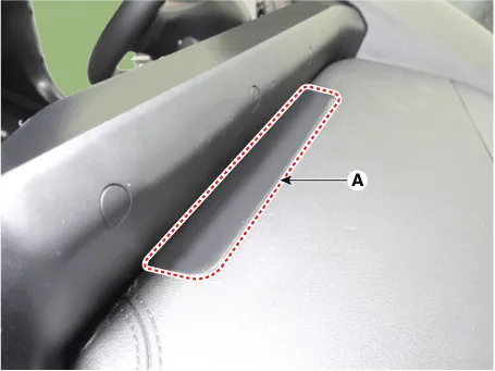
Remove the crash pad garnish [RH]. (Refer to Body - "Crash Pad Garnish") |
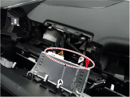
| 3. |
Remove the audio head unit.
|

| Installation |
| 1. |
Install in the reverse order of removal. |
Components and components location Components 1. AVN head unit Schematic diagrams Connector and Terminal Function AVN 5.
Components and components location Components Location 1. Center speaker 2. Tweeter speaker 3. Front midrange speaker 4.
Other information:
Kia Optima DL3 2019-2026 Service and Repair Manual: Power Door Locks
C
Kia Optima DL3 2019-2026 Service and Repair Manual: Walk-in Switch
Components and components location Component Location 1. Walk-in switch Repair procedures Removal When prying with a flat-tip screwdriver or use a prying trim tool, wrap it with protective tape, and apply prote
Categories
- Manuals Home
- Kia Optima Owners Manual
- Kia Optima Service Manual
- Instrument panel overview
- Emergency trunk safety release
- Restraint
- New on site
- Most important about car
