Kia Optima DL3: Audio/AVN System / Speaker
Components and components location
| Components Location |
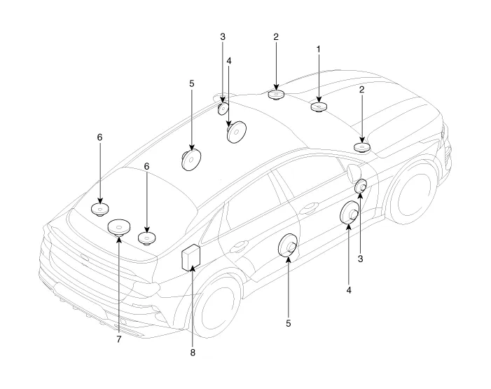
| 1. Center speaker 2. Tweeter speaker 3. Front midrange speaker 4. Front door speaker |
5. Rear door speaker 6. Surround speaker 7. Sub woofer speaker 8. External amplifier |
Repair procedures
| Inspection |
|

Basic inspection
| 1. |
Loosen the screws to rule out the interference from the body trims and surrounding parts and then remove the speaker. |
| 2. |
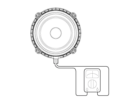
After removing the speaker, check the sound quality of the speaker with the connector plugged in. |
Individual Inspection
| 1. |
Abnormal vibration
|
| 2. |
Noise
|

| 3. |
Poor sound
|
| Removal |
Center Speaker
| 1. |
Disconnect the negative battery terminal. |
| 2. |
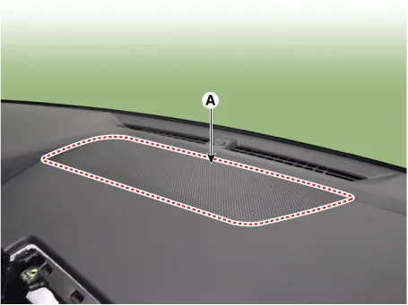
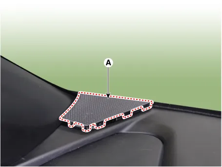
Remove the center speaker grille (A) by using a screwdriver or remover.
|
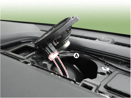
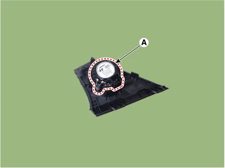
| 3. |
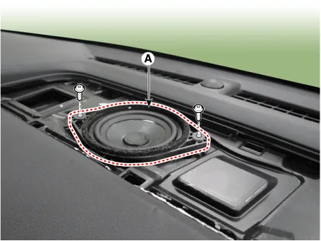
Remove the center speaker (A) after loosening the mounting screws.
|
| 4. |
Disconnect the center speaker connector (A).
|
Tweeter Speaker
| 1. |
Disconnect the negative battery terminal. |
| 2. |
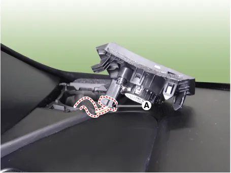
Remove the tweeter speaker grille (A) by using a screwdriver or remover.
|
| 3. |
Disconnect the tweeter speaker connector (A).
|
| 4. |
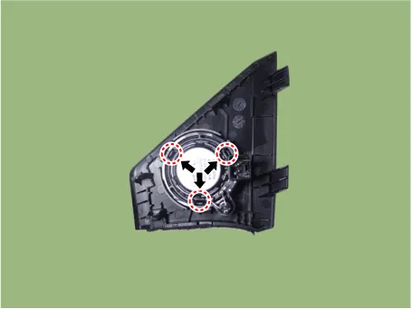
Remove the tweeter speaker (A) by pushing the holder in the direction of arrow.
|
Front Midrange Speaker
| 1. |
Disconnect the negative battery terminal. |
| 2. |
Remove the front door trim. (Refer to Body - "Front Door Trim") |
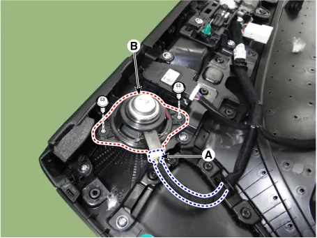
| 3. |
Disconnect the connector (A) and then remove front midrange speaker (B) by loosening the screws.
|
Front Door Speaker
| 1. |
Disconnect the negative battery terminal. |
| 2. |
Remove the front door trim. (Refer to Body - "Front Door Trim") |
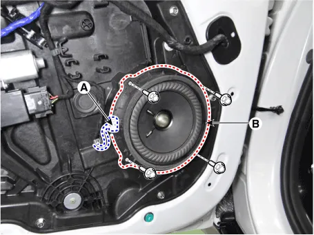
| 3. |
Disconnect the connector (A) and then remove front door speaker (B) by loosening the bolts.
|
Rear Door Speaker
| 1. |
Disconnect the negative battery terminal. |
| 2. |
Remove the rear door trim. (Refer to Body - "Rear Door Trim") |
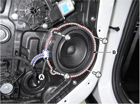
| 3. |
Disconnect the connector (A) and then remove rear door speaker (B) by loosening the bolts.
|
Surround Speaker
| 1. |
Disconnect the negative battery terminal. |
| 2. |
Remove the rear package tray trim. (Refer to Body - "Rear Package Tray Trim") |
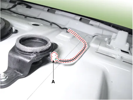
| 3. |
Disconnect the surround speaker connector (A).
|
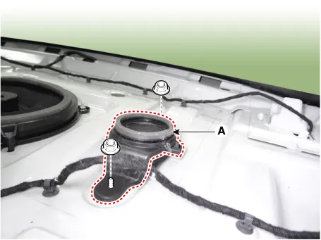
| 4. |
Remove the surround speaker (A) after loosening the mounting nuts.
|
Sub Woofer Speaker
| 1. |
Disconnect the negative battery terminal. |
| 2. |
Remove the rear package tray trim. (Refer to Body - "Rear Package Tray Trim") |
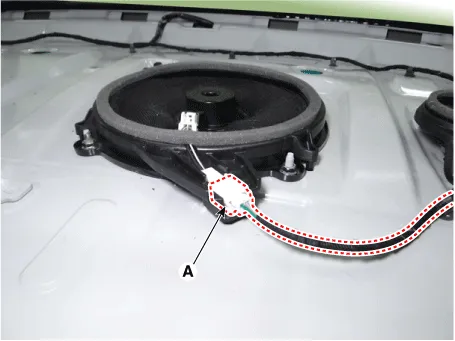
| 3. |
Disconnect the sub woofer speaker connector (A).
|
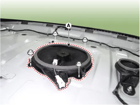
| 4. |
Remove the sub woofer speaker (A) after loosening the mounting nuts.
|
| Installation |
| 1. |
Install in the reverse order of removal. |
Components and components location Components 1. Audio head unit 2. Display audio head unit Schematic diagrams Connector and Terminal Function Audio 4.
Components and components location Component Location 1. External amp Schematic diagrams Connector and Terminal Function Pin Function Connector A Connector B 1 Battery (+) Right front door tweeter speaker (+) 2 Battery (+) Left front door tweeter speaker (+) 3 Battery (+) Sub woofer speaker (+) 4 Battery (+) - 5 - - 6 MM-CAN (High) - 7 MM-CAN (Low) Amplifier navigation voice (+) 8 ACC - 9 - - 10 - - 11 - - 12 Right surround speaker (+) Right rear door speaker (+) 13 Left surround speaker (+) Left rear door speaker (+) 14 Right midrange speaker (+) Center speaker(+) 15 Left midrange speaker (+) - 16 Ground Right front door tweeter speaker (-) 17 Ground Left front door tweeter speaker (-) 18 Ground Sub woofer speaker (-) 19 Ground - 20 Amplifier SPDIF (High) - 21 Amplifier SPDIF (Low) Amplifier navigation voice (-) 22 Amplifier SPDIF (Ground) - 23 - - 24 IGN1 - 25 Right surround speaker (-) Right rear door speaker (-) 26 Left surround speaker (-) Left rear door speaker (-) 27 Right midrange speaker (-) Center speaker (-) 28 Left midrange speaker (-) - Repair procedures Inspection • Warning and guide sounds regarding engine start and driving are generated by the external amplifier.
Other information:
Kia Optima DL3 2019-2026 Service and Repair Manual: License Lamps
Repair procedures Removal 1. Disconnect the negative battery terminal. 2. Remove the lcense lamp (A) by pressing the hook. 3. Disconnect the lcense lamp connector (A).
Kia Optima DL3 2019-2026 Service and Repair Manual: Power Door Lock Switch
Repair procedures Inspection Power Window Main Switch Diagnosis With KDS 1. In the body electrical system, failure can be quickly diagnosed by using the vehicle diagnostic system (KDS). The diagnostic system (KDS) provides the following information.
Categories
- Manuals Home
- Kia Optima Owners Manual
- Kia Optima Service Manual
- Headlamps
- Floor Console Assembly
- Body (Interior and Exterior)
- New on site
- Most important about car
