Kia Optima DL3: Power Train / Automatic Transaxle Fluid
Repair procedures
| Inspection |
Automatic Transaxle Fluid (ATF) Level Check
When checking the ATF level, be careful not to allow foreign substance (like dust) to enter through the filler hole. |

| 1. |
Remove the air cleaner assembly. G 2.0 MPI (Refer to Engine Mechanical System - "Air Cleaner") G 2.5 GDI (Refer to Engine Mechanical System - "Air Cleaner") |
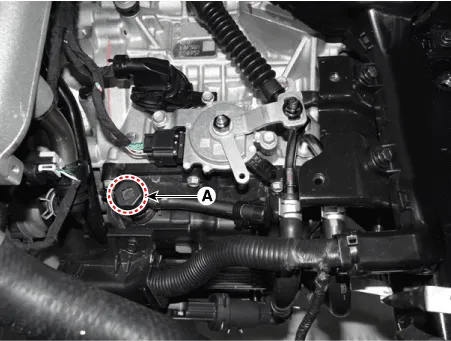
| 2. |
Add 0.7 L of ATF SP-IV through the ATF filler hole after removing the eyebolt (A). [G 2.0 MPI - A6MF1-2]
[G 2.5 GDI - A8MF1]
|

| 3. |
Remove the inhibitor switch. [G 2.0 MPI - A6MF1-2 Only] (Refer to Automatic Transaxle Control System - "Inhibitor Switch") |
| 4. |
Start the engine to warm up the ATF.
|
| 5. |
Check by using KDS that the temperature of the ATF is between 50°C and 60°C (122-140°F). |
| 6. |
Move the shift lever slowly from "P" to "D", then back to "P". Repeat this sequence two times and then move the shift lever to "P" range.
|
| 7. |
Remove the under cover. G 2.0 MPI (Refer to Engine Mechanical System - "Engine Room Under Cover") G 2.5 GDI (Refer to Engine Mechanical System - "Engine Room Under Cover") |
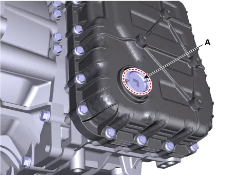
| 8. |
Lift the vehicle and remove the ATF level plug (A) from the valve body cover.
[G 2.0 MPI - A6MF1-2]
[G 2.5 GDI - A8MF1]
|
| 9. |
Check the ATF level.
|
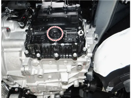
| 10. |
Install the ATF level plug (A).
[G 2.0 MPI - A6MF1-2]
[G 2.5 GDI - A8MF1]
|
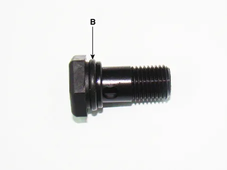
| 11. |
Lower the vehicle and install the eyebolt (A).
[G 2.0 MPI - A6MF1-2]
[G 2.5 GDI - A8MF1]
|
| 12. |
Install the inhibitor switch. [G 2.0 MPI - A6MF1-2 Only] (Refer to Automatic Transaxle Control System - "Inhibitor Switch") |
| 13. |
Install the air cleaner assembly. G 2.0 MPI (Refer to Engine Mechanical System - "Air Cleaner") G 2.5 GDI (Refer to Engine Mechanical System - "Air Cleaner") |
| 14. |
Install the under cover. G 2.0 MPI (Refer to Engine Mechanical System - "Engine Room Under Cover") G 2.5 GDI (Refer to Engine Mechanical System - "Engine Room Under Cover") |
Repair procedures Inspection [On vehicle inspection] 1. Accelerate the engine to about 3,000 rpm 3 times or more.
Repair procedures Inspection Vapor hose 1. Check all the clamps for tightness and the connections for leakage. 2.
Other information:
Kia Optima DL3 2019-2026 Service and Repair Manual: Smart Key Unit
Schematic diagrams Connector and Terminal Function Pin Function Connector A Connector B Connector C Connector D 1 - Front washer switch (Output) - Driver outside handle switch (Input)
Kia Optima DL3 2019-2026 Service and Repair Manual: Compressor
Description and operation Description The compressor is the power unit of the A/C system. It is located on the side of engine block and driven by a V-belt of the engine. The compressor changes low pressure and low temperature refrigerant gas into high pressure and high temperature refrigerant gas.
Categories
- Manuals Home
- Kia Optima Owners Manual
- Kia Optima Service Manual
- Driving your vehicle
- Headlamps
- Engine Mechanical System
- New on site
- Most important about car
