Kia Optima DL3: Blower / Blower Unit
Components and components location
| Component Location |
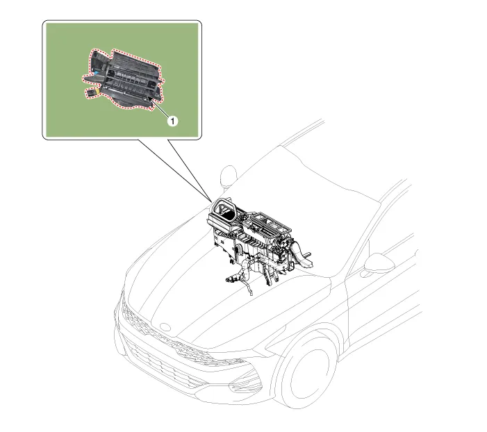
| 1. Blower unit assembly |
| Components |
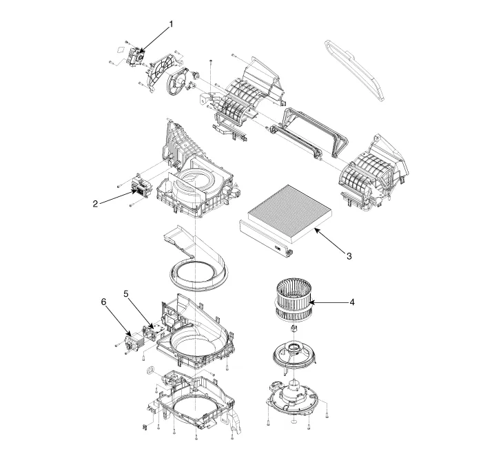
| 1. Intake actuator 2. Cluster ionizer 3. Air filter |
4. Blower motor assembly 5. Resister (Manual) 6. Power mosfet |
Repair procedures
| Replacement |
|

| 1. |
Disconnect the negative (-) battery terminal. |
| 2. |
Recover the refrigerant with a recovery/recycling/charging station. |
| 3. |
When the engine is cool, drain the engine coolant from the radiator. G 2.0 NU MPI (Refer to Engine Mechanical System - "Coolant") G 2.5 GDI THETA II (Refer to Engine Mechanical System - "Coolant") |
| 4. |
Remove the cowl top cover. (Refer to Body - "Cowl Top Cover") |
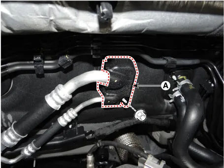
| 5. |
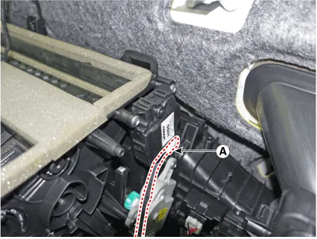
Loosen the mounting nut and remove the expension valve cover (A).
|
| 6. |
Loosen the mounting bolts and separate the expension valve (A) from the evaporator core.
|
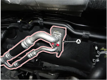

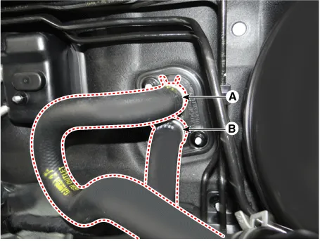
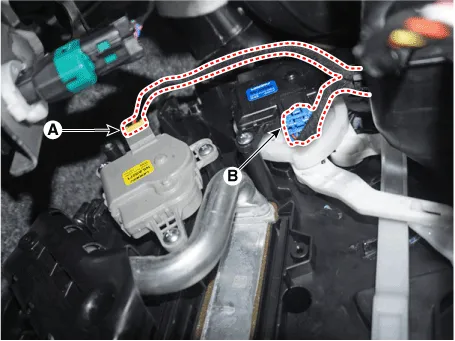
| 7. |
Separate the heater hose (A) and (B).
|
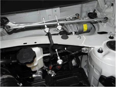
| 8. |
Loosen the cowl cross bar mounting bolts.
|
| 9. |
Remove the front seat assembly. (Refer to Body - "Front Seat Assembly") |
| 10. |
Remove the floor console assembly. (Refer to Body - "Floor Console Assembly") |
| 11. |
Remove the crash pad center panel. (Refer to Body - "Crash Pad Ceter Panel") |
| 12. |
Remove the front pillar trim. (Refer to Body - "Front Pillar Trim") |
| 13. |
Remove the cowl side trim. (Refer to Body - "Cowl Side Trim") |
| 14. |
Remove the steering column shroud lower panel. (Refer to Body - "Steering Column Shroud Panel") |
| 15. |
Remove the steering wheel. (Refer to Steering System - "Steering Wheel") |
| 16. |
Remove the multifunction switch. (Refer to Body Electrical System - "Multifunction Switch") |
| 17. |
Lower the steering column after loosening the mounting bolts. (Refer to Steering System - "Steering Column and Shaft") |
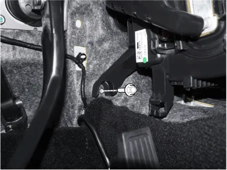
| 18. |
Remove the accelerator pedal. (Refer to Engine Control/Fuel System - "Accelerator Pedal") |
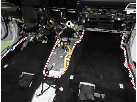
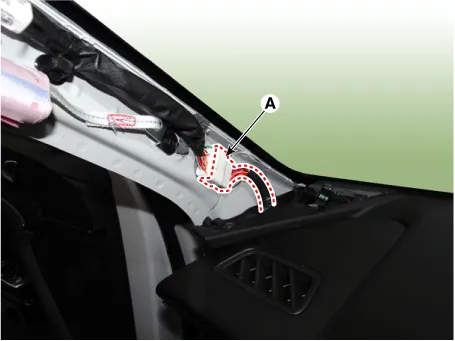
| 19. |
Separate the floor carpet (A) to obtain space for removing the rear heating duct.
|
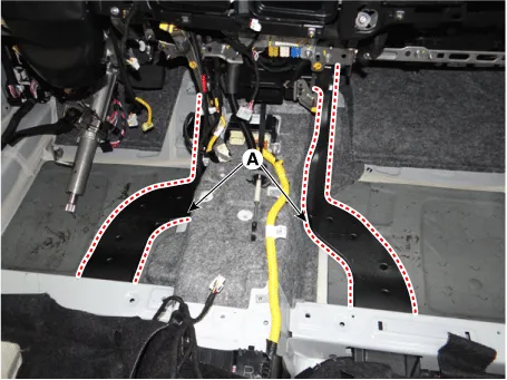
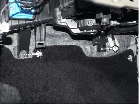
| 20. |
Remove the rear heating duct (A).
|
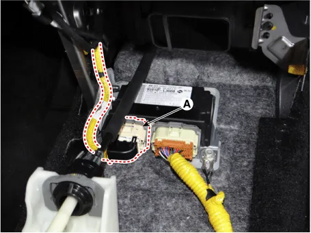
| 21. |
Separate the airbag control module (SRSCM) connector (A).
|
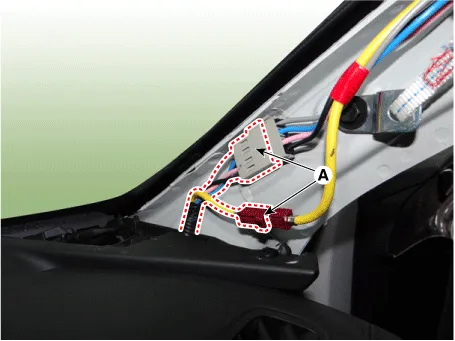
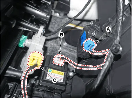
| 22. |
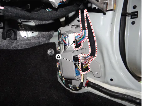
Loosen the front pillar mounting clips and separate the connectors (A). [LH]
[RH]
|
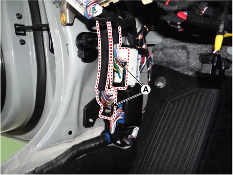
| 23. |
Separate the junction box connectors (A).
|

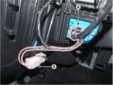
| 24. |
Separate the multi box connectors (A). [LH]
[RH]
|
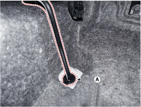
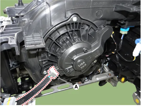
| 25. |
Remove the drain hose (A).
|
| 26. |
Remove the lower mounting bolt of the blower unit.
[LH]
[RH]
|
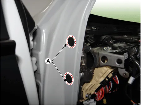
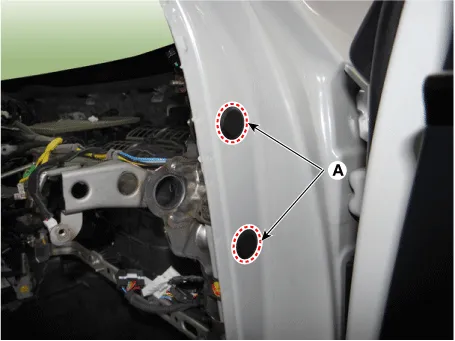
| 27. |
Remove the plug holes (A). |
| 28. |
Loosen the cowl cross bar side mounting bolts. [LH]
[RH]
|
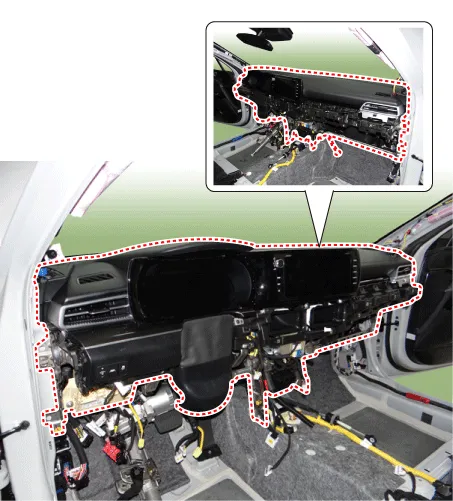
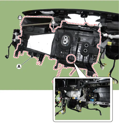
| 29. |
After loosening the bolts and nuts remove the crash pad and heater & blower unit assembly (A) together.
|
| 30. |
Remove the integrated body control unit. (Refer to Body Electrical System - "Integrated Body Control Unit (IBU)") |
| 31. |
Remove the heater control unit. (Refer to Heating,Ventilation And Air Conditioning - "Heater Control Unit") |
| 32. |
Separate the heater & blower unit connectors and wiring. [LH]
[RH]
|
| 33. |
Loosen the mounting nuts, bolts and remove the heater & blower unit (A) from the crash pad.
|
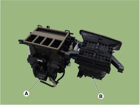
| 34. |
Loosen the mounting screws, separate the heater unit (A) and blower unit (B).
|
| 35. |
To install, reverse the removal procedure.
|

Repair procedures Inspection 1. Connect the battery voltage and check the blower motor rotation. 2.
Other information:
Kia Optima DL3 2019-2026 Service and Repair Manual: Ventilated and Heated Seat Switch
Schematic diagrams Connector and Terminal Function [Front Seat] [Ventilation+Heater Type / Non-Heater Type] Pin Function Pin Function Ventilation+Heater Type Non-Heater Type Ventilation+Heater Type Non-Heater Type
Kia Optima DL3 2019-2026 Service and Repair Manual: Heating, Ventilation and Air Conditioning
Service data Service Data Air Conditioner ltem Specification Compressor Type 6SAS14 Oil type & Capacity ND-OIL 12 80 ± 10 cc (2.82 ± 0.
Categories
- Manuals Home
- Kia Optima Owners Manual
- Kia Optima Service Manual
- Engine Control / Fuel System
- Body (Interior and Exterior)
- Suspension System
- New on site
- Most important about car
