Kia Optima DL3: Engine Electrical System / Charging System
Components and components location
| Components |
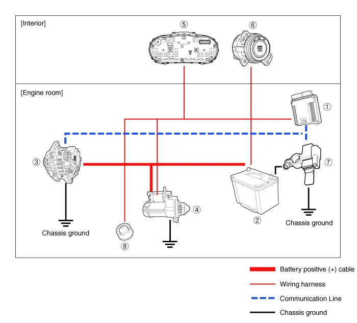
① ECM
② Battery
③ Alternator
④ Starter
⑤ Instrument Cluster
⑥ Ignition switch or start/stop button
⑦ Battery sensor
⑧ Hood switch
Description and operation
| Description |
The charging system included a battery, an alternator with a built-in regulator, and the charging indicator light and wire.
The Alternator has eight built-in diodes, each rectifying AC current to DC current.
Therefore, DC current appears at alternator "B" terminal.
In addition, the charging voltage of this alternator is regulated by the battery voltage detection system.
The alternator is regulated by the battery voltage detection system. The main components of the alternator are the rotor, stator, rectifier, capacitor brushes, bearings and V-ribbed belt pulley. The brush holder contains a built-in electronic voltage regulator.
| Alternator Management System |
Alternator management system controls the charging voltage set point in order to improve fuel economy, manage alternator load under various operating conditions, keep the battery charged, and protect the battery from over-charging. ECM controls generating voltage by duty cycle (charging control, discharging control, normal control) based on the battery conditions and vehicle operating conditions.
The system conducts discharging control when accelerating a vehicle. Vehicle reduces an alternator load and consumes an electric power form a battery.
The system conducts charging control when decelerating a vehicle. Vehicle increases an alternator load and charges a battery.
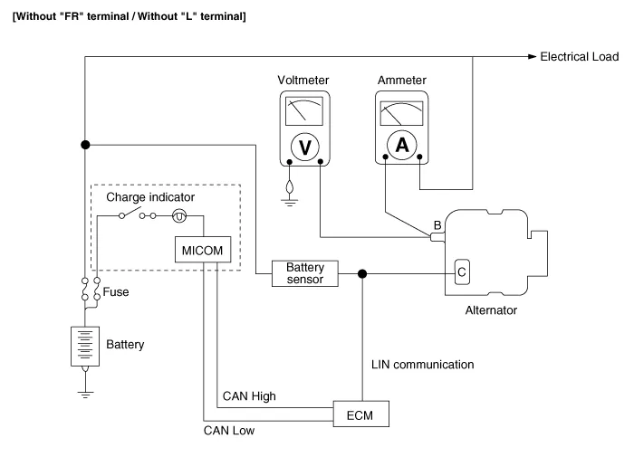
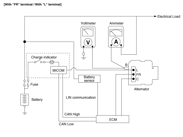
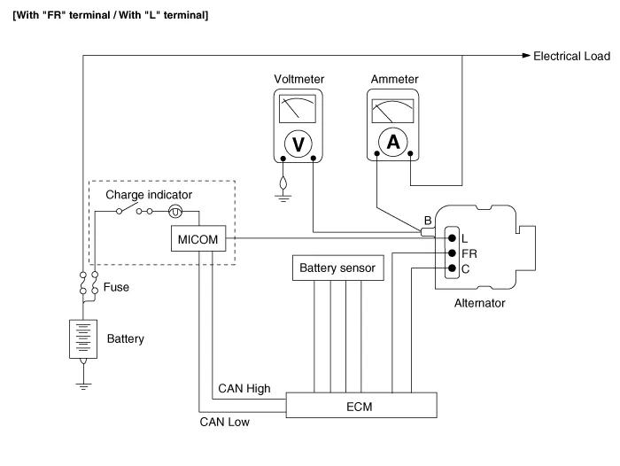
Schematic diagrams
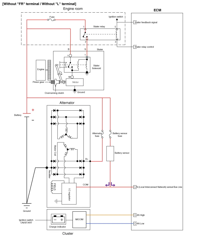
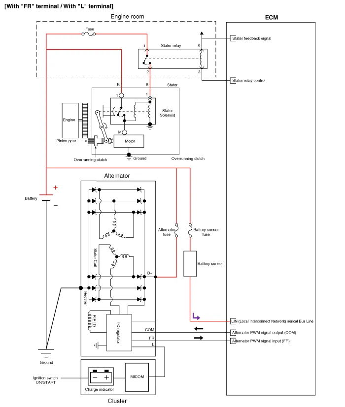
| Circuit Diagram |

Repair procedures
| Inspection |
| Inspection Item |
| • |
Battery efficiency inspection |
| • |
Battery voltage inspection |
| • |
Charging voltage insptection |
| • |
General inspection |
| • |
Terminal tightening state inspection |
| • |
Engine/ transaxle ground state inspection |
| • |
Wiring harness ground state inspection |
| • |
Electrical Specified Value Inspection |
| • |
Vehicle parasitic current inspection |
| • |
Battery capacity inspection |
Battery Efficiency Inspection
|

|

Battery Voltage Inspection
| 1. |
After having driven the vehicle and in the case that 20 minutes have not passed after having stopped the engine, turn the ignition switch ON and turn on the electrical system (headlamp, blower motor, rear defogger etc.) for 60 seconds to remove the surface charge. |
| 2. |
Turn the ignition switch OFF and turn off the electrical systems. |
| 3. |
Measure the battery voltage between the negative (-) and positive (+) terminals of the battery.
If the voltage is less than specification, charge the battery. |
General Inspection
| 1. |
Check that the battery terminals are not loose or corroded. (Refer to Charging System - "Battery") |
| 2. |
Check the fuses for continuity.
|
| 3. |
Inspect Drive Belt
|
| 4. |
Measure and adjust drive belt tension. (Refer to Engine Mechanical System - "Drive Belt") |
| 5. |
Visually check alternator wiring and listen for abnormal noises.
|
| 6. |
Check Discharge Warning Light Circuit
|
Terminal Tightening State Inspection
|
| Inspection Component Location |
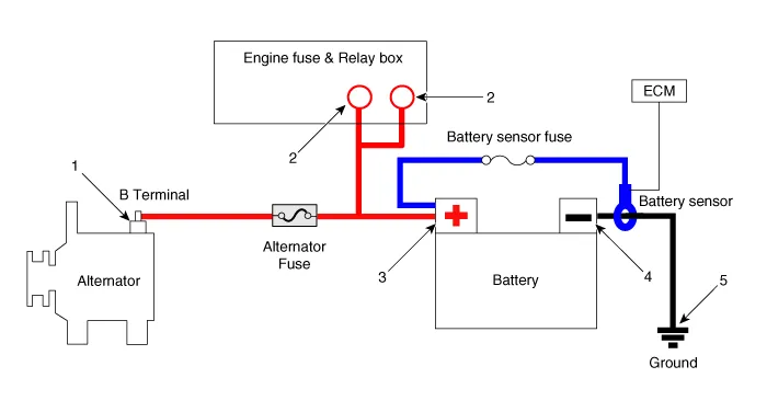
| 1. Alternator B+ terminal 2. Engine room fuse & relay box positive (+) terminal 3. Battery negative (+) terminal |
4. Battery negative (-) terminal 5. Chassis ground |
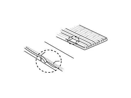
Engine/ Transaxle Ground State Inspection
|
Wiring harness ground state inspection
|
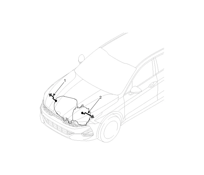
| 1. Engine ground (Engine ↔ Chassis) 2. Transaxle ground (Transaxle ↔ Chassis) |
Check the ground point. (Refer to ETM Harness Layout - "Ground Point") |
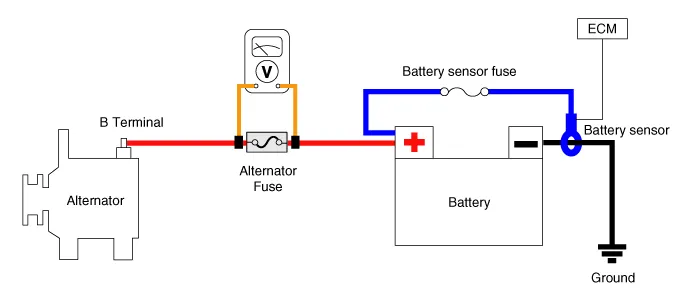
Electrical Specified Value Inspection (Using the Voltmeter and Ammeter)
| 1. |
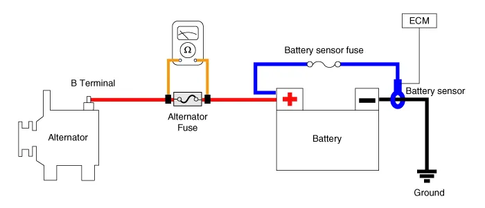
Voltage Drop Test of Alternator Output Wire This test determines whether or not the wiring between the alternator "B" terminal and the battery (+) terminal is good by the voltage drop method.
|
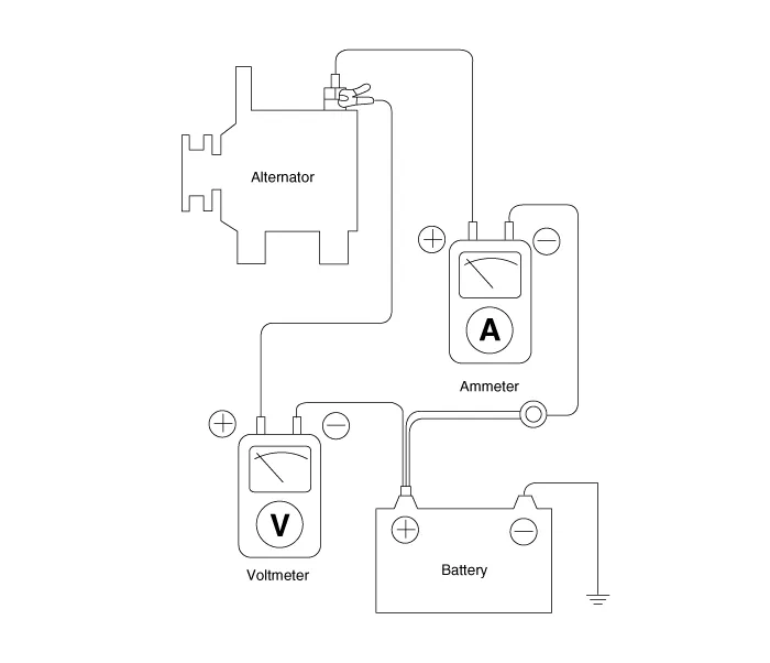
| 2. |
Output Current Test This test determines whether or not the alternator gives an output current that is equivalent to the normal output.
|

| 3. |
Regulated Voltage Test The purpose of this test is to check that the electronic voltage regulator controls voltage correctly.
|
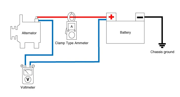
Electrical Specified Value Inspection (Using the Voltmeter and Clamp type Ammeter)
| 1. |
Voltage Drop Test of Alternator Output Wire This test determines whether or not the wiring between the alternator "B" terminal and the battery (+) terminal is good by the voltage drop method.
|
| 2. |
Output Current Test This test determines whether or not the alternator gives an output current that is equivalent to the normal output.
|
| 3. |
Regulated Voltage Test The purpose of this test is to check that the electronic voltage regulator controls voltage correctly.
|
Vehicle parasitic current inspection
[Using the Ammeter]
| 1. |
Turn the all electric devices OFF, and then turn the ignition switch OFF. |
| 2. |
Close all doors except the engine hood, and then lock all doors.
|
| 3. |
Wait for a few minutes until the vehicle’s electrical systems go to sleep mode.
|
| 4. |
Connect an ammeter in series between the battery (-) terminal and the ground cable, and then disconnect the clamp from the battery (-) terminal slowly.
|

| 5. |
Read the current value of the ammeter.
|
[Using the Clamp type Ammeter]
| 1. |
Turn the all electric devices OFF, and then turn the ignition switch OFF. |
| 2. |
Close all doors except the engine hood, and then lock all doors.
|
| 3. |
Wait for a few minutes until the vehicle’s electrical systems go to sleep mode.
|
| 4. |
Install the clamp type ammerter on battery negative (-) terminal.
|

| 5. |
Read the current value of the ammeter.
|
Troubleshooting
| Troubleshooting |
|
|
Symptom |
Suspected Area |
Remedy |
|
Charging warning lamp does not turn on during IG ON. |
Broken alternator main fuse |
Inspect / Repair / Replace fuse. |
|
Broken instrument cluster fuse |
Inspect / Repair / Replace fuse. |
|
|
Broken instrument cluster internal bulb |
Inspect / Repair / Replace instrument cluster. |
|
|
Defective connection of wiring connector |
Inspect / Repair / Replace wiring connection. |
|
|
Defective voltage regulator or alternator |
Inspect / Repair / Replace voltage regulator or alternator. |
|
|
Defective connection of battery terminal |
Inspect tightening of (+) and (-) battery terminals to specified torque. |
|
|
Communication error |
Inspect wiring between regulator and ECM. |
|
|
Inspect transmission signal of ECM. |
||
|
Inspect / Repair / Replace alternator if the wiring and ECM are normal. |
||
|
Charging warning lamp does not turn off during engine running. |
Worn drive belt or lack of tension |
Inspect / Repair / Replace drive belt. |
|
Defective connection, corroded or worn battery cable |
Inspect connection of battery cable and Inspect / Repair / Replace cable. |
|
|
Broken alternator main fuse |
Inspect / Replace alternator main fuse or battery cable. |
|
|
Defective voltage regulator or alternator |
Inspect / Replace voltage regulator or alternator. |
|
|
Defective wiring |
Inspect / Replace wiring. |
|
|
Defective instrument cluster |
Inspect / Replace instrument cluster |
|
|
Slip in alternator pulley |
Inspect / Replace alternator pulley. |
|
|
Adjust tension / Replace drive belt. |
||
|
Defective connection of battery terminal |
Inspect tightening of (+) and (-) battery terminals to specified torque. |
|
|
Charging warning lamp turns on. |
Slip, worn or lack of tension in drive belt |
Adjust tension / Replace drive belt. |
|
Inspect / Replace auto tensioner (only for auto tensioner type). |
||
|
Error in Alternator Management System (AMS) voltage |
Inspect battery sensor connecting harness and connection with body. |
|
|
Error in battery sensor |
Inspect / Repair / Replace battery sensor. |
|
|
Short between battery sensor wiring and body |
Inspect / Repair / Replace battery sensor. |
|
|
Defective alternator L terminal output power |
Inspect / Repair / Replace alternator or regulator. |
|
|
Degradation due to defective contact of battery (+) terminal |
Check tightening to specified torque / Inspect / Repair / Replace battery
wiring. |
|
|
Short in alternator connecting extension connector internal pin |
Inspect / Repair / Replace wiring. |
|
|
|
Short circuit between body and mission ground |
Inspect / Repair / Replace ground. |
|
Communication error |
Inspect / Repair / Replace wiring between regulator and ECM. |
|
|
Inspect transmission signal of ECM. |
||
|
Inspect / Repair / Replace alternator if wiring and ECM are normal. |
||
|
Short in the middle of connection to alternator L terminal (L terminal applied vehicle model) |
Inspect / Repair / Replace wiring. |
|
|
Drive belt rotation stops due to slip in crankshaft damper pulley or defective
pulley. |
Inspect or replace crankshaft damper pulley / Inspect, repair or replace
drive belt tensioner bearing. |
|
|
Slip, worn or lack of tension in drive belt |
Adjust tension / Inspect / Repair / Replace drive belt. |
|
|
Defective voltage regulator |
Inspect / Repair / Replace voltage regulator. |
|
|
Defective alternator |
Inspect / Repair / Replace alternator. |
|
|
Broken alternator main fuse |
Inspect / Repair / Replace alternator main fuse or battery wiring cable. |
|
|
Defective ground |
Inspect / Repair / Replace ground. |
|
|
Discharged battery |
Adjust tension / Inspect / Repair / Replace drive belt. |
|
|
Inspect / Repair / Replace wiring connection. |
||
|
Inspect / Repair / Replace alternator main fuse. |
||
|
Inspect / Repair / Replace alternator. |
||
|
Inspect / Repair / Replace voltage regulator. |
||
|
Inspect / Repair / Replace battery unit. |
||
|
Inspect for dark current / Repair / Replace. |
||
|
Learn / Inspect / Repair / Replace battery sensor. |
||
|
Inspect for short / Repair / Replace battery cable. |
||
|
Inspect / Repair / Replace ECM. |
||
|
Inspect / Repair / Replace body electrical related parts. |
||
|
Inspect / Repair / Replace installation status of alternator connector. |
||
|
Inspect / Repair / Replace tightening of (+) and (-) battery terminals to
specified torque. |
||
|
Swollen battery |
Defective battery |
Inspect / Replace battery. |
|
Defective voltage regulator or alternator |
Inspect / Repair / Replace voltage regulator or alternator. |
|
|
Defective charging related parts or wiring |
Inspect / Repair / Replace charging related parts and wiring. |
|
|
After inspection, repair or replace related parts in case of malfunction. |
||
Description and operation Description A spark plug is a device for delivering electric current from an ignition system to the combustion chamber of a spark-ignition engine to ignite the compressed fuel/air mixture therein by means of an electric spark, while containing combustion pressure within the engine.
Description and operation Description The Alternator has eight built-in diodes, each rectifying AC current to DC current. Therefore, DC current appears at alternator "B" terminal.
Other information:
Kia Optima DL3 2019-2026 Service and Repair Manual: Power Seat Motor
Components and components location Components 1. Lumbar support motor 2. Reclining motor 3. Front height motor 4. Rear height motor 5. Slide motor Repair procedures Inspection 1.
Kia Optima DL3 2019-2026 Service and Repair Manual: Wiper Motor
Schematic diagrams Connector and Terminal Function Pin Function 1 Ground (-) 2 Parking 3 Power (+) 4 Low 5 High Repair procedures Remova
Categories
- Manuals Home
- Kia Optima Owners Manual
- Kia Optima Service Manual
- Timing Chain
- Headlamps
- Heating, Ventilation and Air Conditioning
- New on site
- Most important about car
