Kia Optima DL3: Charging System / Alternator
Description and operation
| Description |
The Alternator has eight built-in diodes, each rectifying AC current to DC current.
Therefore, DC current appears at alternator "B" terminal.
In addition, the charging voltage of this alternator is regulated by the battery voltage detection system.
The alternator is regulated by the battery voltage detection system.
The main components of the alternator are the rotor, stator, rectifier, capacitor brushes, bearings and V-ribbed belt pulley.
The brush holder contains a built-in electronic voltage regulator.
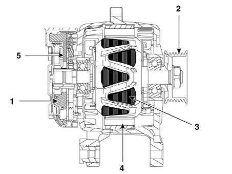
| 1. Brush 2. General pulley 3. Rotor 4. Stator 5. Rectifier |
| 1. Brush 2. OAP pulley 3. Rotor 4. Stator 5. Rectifier |
Specifications
| Specification |
|
Item |
Specification |
|
|
Rated voltage |
13.5V, 120A |
|
|
Speed in use |
1,000 - 18,000 rpm |
|
|
Voltage regulator |
IC Regulator built-in type |
|
|
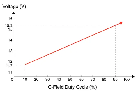
Regulator Setting Voltage |
External mode |
Refer to below graph |
|
Internal mode |
14.55 ± 0.3V |
|
|
Temperature Gradient |
External mode |
0 ± 3 mV / °C |
|
Internal mode |
-3.5 ± 2mV / °C |
|
Components and components location
| Components |
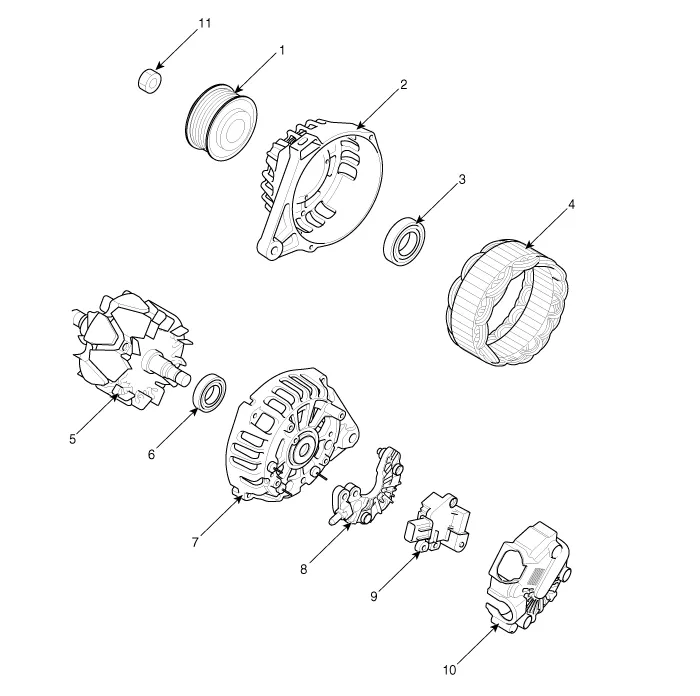
| 1. Pully
2. Front Housing 3. Front Bearing 4. Stator 5. Rotor 6. Rear Bearing |
7. Rear
Housing 8. Rectifier Assembly 9. Regulator Assembly 10. Rear Cover 11. Nut |
Schematic diagrams
| Circuit Diagram |
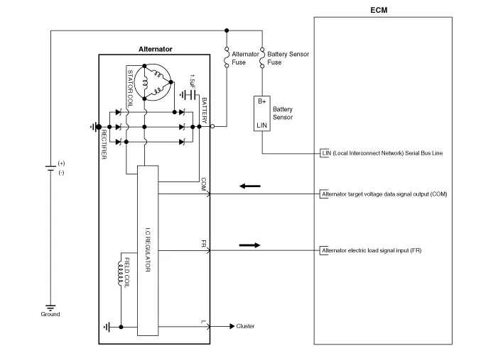
|

Repair procedures
| Removal |
| 1. |
Disconnect the negative battery (-) terminal. |
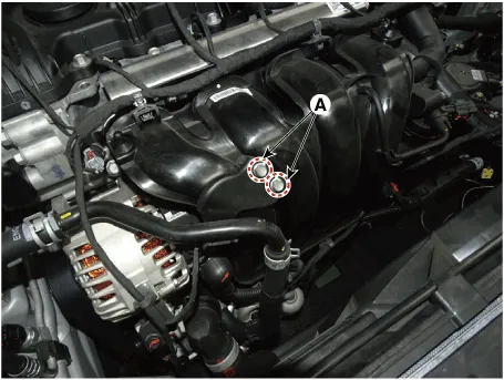
| 2. |
Remove the water pipe bracket bolts (A).
|
| 3. |
Remove the drive belt. (Refer to Engine Mechanical System - "Drive Belt") |
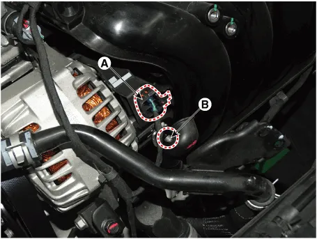
| 4. |
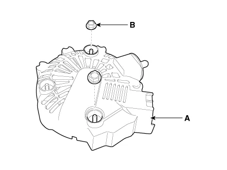
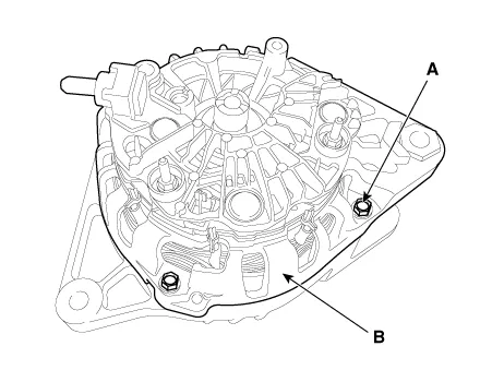
Disconnect the alternator connector (A) and the cable nut (B) from alternator "B" terminal.
|
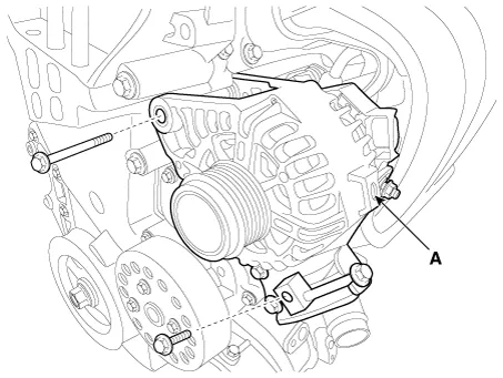
| 5. |
Pull out the through bolt and then remove the alternator (A).
|
| Installation |
| 1. |
Install in the reverse order of removal. |
| Disassembly |
| 1. |
Loosen the nuts (B) and then remove the cover (A).
|
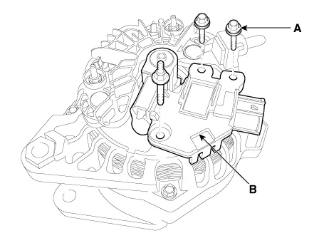
| 2. |
Loosen the mounting bolts (A) and remove the regulator assembly (B).
|
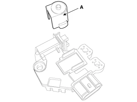
| 3. |
Remove the slip ring guide (A).
|
| 4. |
Remove the OAP cap. (with OAP) |
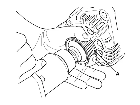
| 5. |
Remove the alternator pulley (A) after loosening the mounting nut. (with out OAP)
|
| 6. |
Loosen the bolts (A) and then remove the rear housing (B).
|
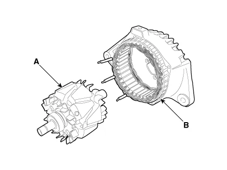
| 7. |
Disconnect the rotor (A) and the housing (B).
|
| 8. |
Reassembly is the reverse order of disassembly. |
| Reassembly |
| 1. |
Reassemble in the reverse order of disassembly. |
When reassembling OAD pulley, replace with new OAD cap. |

| Inspection |
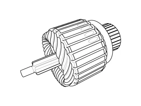
| [Rotor] |
| 1. |
Check that there is continuity between the slip rings (C). |
| 2. |
Check that there is no continuity between the slip rings and the rotor (B) or rotor shaft (A).
|
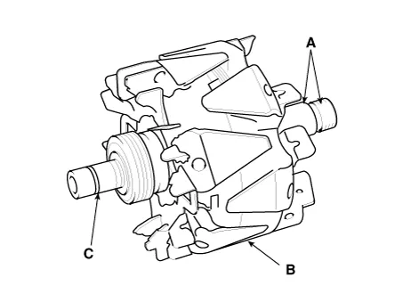
| 3. |
If the rotor fails either continuity check, replace the alternator. |
| [Stator] |
| 1. |
Check that there is continuity between each pair of leads (A).
|

| 2. |
Check that there is no continuity between each lead and the coil core. |
| 3. |
If the coil fails either continuity check, replace the alternator. |
Components and components location Components ① ECM ② Battery ③ Alternator ④ Starter ⑤ Instrument Cluster ⑥ Ignition switch or start/stop button ⑦ Battery sensor ⑧ Hood switch Description and operation Description The charging system included a battery, an alternator with a built-in regulator, and the charging indicator light and wire.
Description and operation Description 1. The CMF(Closed Maintenance Free) battery is, as the name implies, totally maintenance free and has no removable battery cell caps.
Other information:
Kia Optima DL3 2019-2026 Service and Repair Manual: Overhead Console Lamp
Schematic diagrams Connector and Terminal Function [A Type] Connector A Pin E xcept Russia Region Russia only Function Function 1 Battery (+) Battery (+)
Kia Optima DL3 2019-2026 Service and Repair Manual: Auto Defoging Actuator
Components and components location Components Location 1. Auto logging actuator Description and operation Description The auto defogging sensor is installed on front window glass. The sensor judges and sends signal if moisture occurs to blow out wind for defogging.
Categories
- Manuals Home
- Kia Optima Owners Manual
- Kia Optima Service Manual
- Headlamps
- Body (Interior and Exterior)
- Engine Control / Fuel System
- New on site
- Most important about car
