Kia Optima DL3: Engine Mechanical System / Cylinder Head Assembly
Components and components location
| Components |
|
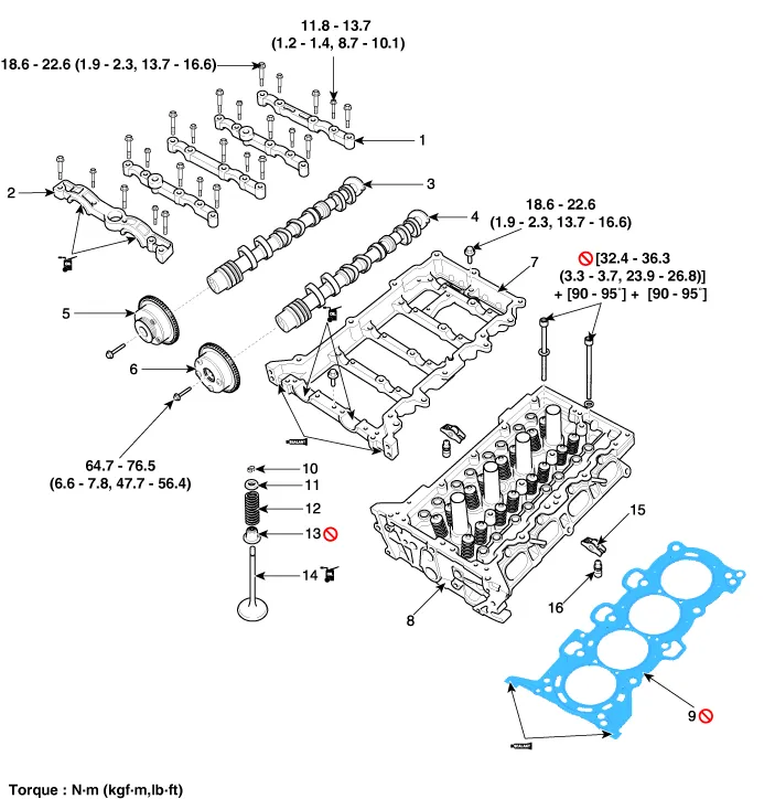
1. Camshaft bearing cap 2. Camshaft front bearing cap 3. Exhaust camshaft 4. Intake camshaft 5. Exhaust CVVT assembly 6. Intake CVVT assembly |
7. Cam carrier 8. Cylinder head 9. Cylinder head gasket 10. Retainer lock 11. Retainer 12. Valve spring |
13. Valve stem seal 14. Valve 15. Swing arm 16. Hydraulic lash adjuster (HLA) |
Repair procedures Disassembly • Use fender covers to avoid damaging painted surfaces.
Components and components location Components 1. Cylinder head cover 2. Cylinder head cover gasket Repair procedures Removal • Use fender covers to avoid damaging painted surfaces.
Other information:
Kia Optima DL3 2019-2026 Service and Repair Manual: Integrated Memory Seat (IMS) Unit
Specifications Specifications Item Specifications Rated voltage DC 12 V Operating voltage DC 9 - 16 V Operating temperature range -22 to 167°F (-30 to 75°C) Dark current Max.
Kia Optima DL3 2019-2026 Service and Repair Manual: Power Window Switch
Schematic diagrams Connector and Terminal Function Power Window Main Switch Pin Function 1 B-CAN (Low) 2 B-CAN (High) 3 Ground (Assist safety) 4 Assist safety 5
Categories
- Manuals Home
- Kia Optima Owners Manual
- Kia Optima Service Manual
- Suspension System
- Emergency trunk safety release
- Engine Control / Fuel System
- New on site
- Most important about car
