Kia Optima DL3: Cylinder Head Assembly / Cylinder Head Cover
Components and components location
| Components |
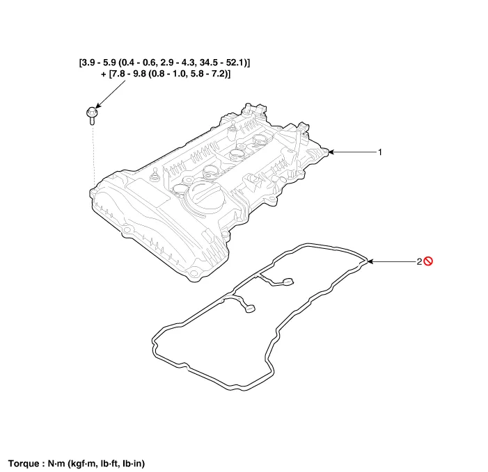
| 1. Cylinder head cover |
2. Cylinder head cover gasket
|
Repair procedures
| Removal |
|

Mark all wiring and hoses to avoid misconnection. |

| 1. |
Remove the engine cover. (Refer to Engine and Transaxle Assembly - "Engine Cover") |
| 2. |
Disconnect the battery negative terminal. |
| 3. |
Disconnect the wiring connectors and harness clamps and remove the connector brackets around the cylinder head cover.
|
| 4. |
Remove the air cleaner assembly. (Refer to Intake and Exhaust System - "Air Cleaner") |
| 5. |
Remove the ignition coils. (Refer to Engine Electrical System - “Ignition Coil”) |
| 6. |
Remove the engine oil level gauge. (Refer to Lubrication System - “Oil Level Gauge & Pipe”) |
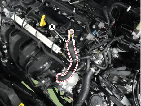
| 7. |
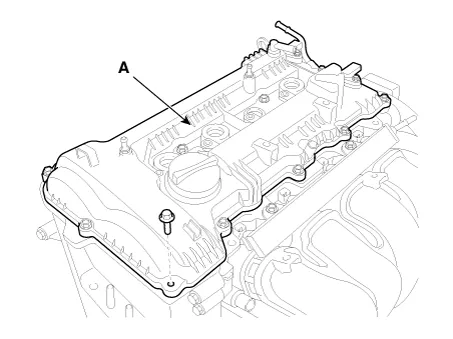
Disconnect the positive crankcase ventilation (PCV) hose (A).
|
| 8. |
Remove the cylinder head cover (A).
|

| Installation |
| 1. |
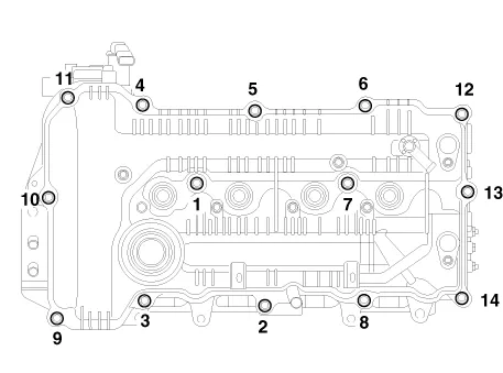
Install cylinder head cover.
|
| 2. |
Install the other parts reverse order of removal. |
Components and components location Components 1. Camshaft bearing cap 2. Camshaft front bearing cap 3. Exhaust camshaft 4.
Components and components location Components 1. Camshaft bearing cap 2. Camshaft front bearing cap 3. Exhaust camshaft 4.
Other information:
Kia Optima DL3 2019-2026 Service and Repair Manual: Fog Lamp
Repair procedures Removal Front Fog Lamp 1. Disconnect the negative battery terminal. 2. Remove the front bumper assembly. (Refer to Body - "Front Bumper Assembly") 3.
Kia Optima DL3 2019-2026 Service and Repair Manual: Heater Control Unit
Components and components location Components Connector Pin Function [Connector A] Pin NO Funtion Pin NO Funtion 1 Ground 11 Ground 2 Clean signal 12 -
Categories
- Manuals Home
- Kia Optima Owners Manual
- Kia Optima Service Manual
- Heating, Ventilation and Air Conditioning
- Cooling System
- Body (Interior and Exterior)
- New on site
- Most important about car
