Kia Optima DL3: Parking Brake System / Electric Parking Brake (EPB)
Description and operation
The electronic parking brake (EPB) is different from existing parking systems
which operated with the brake pedal or the lever type. The EPB system sends the
signal to the ECU when a driver operates the EPB switch. The ECU operates the EPB
actuator composed with motor gears. The braking power is caused by occurs when the
motor pulls the cable connected the brake system.
The EPB ECU is one of the parts of EPB system. It perceives the signal of the
various sensor of system, executes a self diagnosis, controls EPB system with the
logic.
Main Function
| 1. |
Static Braking Mode
The operation and the cancellation at the stop condition of the vehicle
| (1) |
The operation condition: Pull the EPB switch irrespective of
the brake pedal pressed condition. (Pull).
| –
|
The Vehicle speed <= 3kph
|
|
| (2) |
The cancellation condition: Push the EPB switch at the ignition
switch on & the brake pedal pressed condition. (Push).
|
|
| 2. |
Dynamic Braking Function
Dynamic Braking Function (DBF) : The DBF is the braking function at the
driving condition, it can operate the EPB system and cancel it at the vehicle
driving condition. This function will be used while foreign materials get
in between the brake pedal or the brake hydraulic line can not be operated.
| (1) |
The operation condition
It operated only when the vehicle speed is faster than 3kph and
the EPB switch is pushed.
|
| (2) |
The cancellation condition: It canceled when the pulling of the
EPB switch is stopped.
|
| (3) |
Principle of Operation
| –
|
ESP system is normal condition: EPB requests applying
pressure of brake to ESP system.
|
| –
|
ESP system is abnormal condition: EPB operates the parking
brake for reduction of speed.
|
|
| (4) |
Peculiarity
Anti-lock is operated when occurring wheel lock. Parking lamp
on the cluster illuminates in the case of emergency braking.
|
|
| 3. |
Drive Away Release
Convenient for drivers, EPB is automatically released when driver shift
from P into another (R/N/D/S) during braking.
|
| 4. |
Latching Run
This is reconnection function to operate EPB normally after emergency
release.
Operation
| (1) |
After emergency release, when operating EPB first, the hook connects
to the claw in the EPB with operating parking brake with maximum
cable tension.
|
| (2) |
Reconnection function can be performed with the GDS.
|
| (3) |
After testing for reconnection 5 times, EPB isn’t be operated
in the present ignition switch cycle when EPB doesn’t reconnect
normally.
|
|
| 5. |
Bedding Mode
You must do "Bedding in process" for optimizing the initial operation
performance of EPB after replacing the parking brake shoe and rear brake
disc.
Bedding in Process
| (1) |
Ignition on, start engine.
|
| (2) |
Apply the foot brake 2 times within 10 seconds and hold applied
after the last application.
|
| (3) |
Apply the EPB switch 4 times, followed by 3 release applications
within 10 seconds.
|
| (4) |
The linings must be bedded-in by 6 repeated dynamic braking procedures
from 30-35 km/h to vehicle standstill. (If the vehicle speed is
over 50 km/h at the Bedding Mode, it is automatically released.)
|
| (5) |
After each braking cycle a cooling period for the linings is
necessary to prevent lining damage.
| –
|
The cooling can either be carried out via driving a 500
m distance after each braking cycle without any apply of
the EPB or via keeping the vehicle in standstill for 1 minute
after each braking.
|
|
|
| 6. |
AVH (Automatic Vehicle Hold)
AVH supports to keep a stop condition of the vehicle by hydraulic brake
at a stop.
| (1) |
Condition for operation
| –
|
Fastening driver seat belt
|
| –
|
A gear shift is not P-range
|
| –
|
Perfect stop condition with hitting the brake pedal.
|
|
| (2) |
AVH function holds stop condition of the vehicle for maximum
5 minutes.
VDC valve keeps stop condition because of intercept the oil passage
with pressure occurred from brake pedal.
|
| (3) |
An accumulated time of AVH operation : Max. 30min
|
| (4) |
Automatic release function
AVH mode is released when driver attempts starting a vehicle
by pedaling an acceleration pedal at the D/ S/ R range.
|
| (5) |
Automatically convert AVH to EPB
AVH will convert EPB operation automatically if any one satisfy
conditions below.
[Normal conversion case]
| –
|
In the case of driver door open & Driver seat belt release
at the same time
|
| –
|
In the case of opening the hood while the shift lever
is D or S.
|
| –
|
In the case of opening the trunk while the shift lever
is R
|
| –
|
In the case of over 5 minutes of AVH operation time
|
| –
|
Stop at a slope of twenty five degrees
|
[Abnormal conversion case]
| –
|
When sensing detailed motion of the vehicle.
|
| –
|
When sensing the fault of ESP hydraulic system.
|
|
|
Warning Lamp
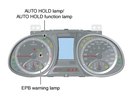
| 1. |
EPB warning lamp
EPB warning lamp indicates the EPB cut and malfunction.
EPB warning lamp comes ON below cases.
| (1) |
EPB warning lamp comes on for 3 seconds after the ignition switch
is ON. If EPB system is working properly, EPB warning lamp goes
OFF
|
| (2) |
If EPB system is not working properly, EPB warning lamp comes
ON
|
| (3) |
Under diagnosis mode, EPB warning lamp comes ON
|
|
| 2. |
AUTO HOLD lamp / AUTO HOLD function lamp
| (1) |
AUTO HOLD switch ON
| A. |
Brake system operates automatically when vehicle speed
is "0", in the case of parking or waiting at a red light,
during braking (AUTO HOLD function lamp : Green)
|
| B. |
Brake system is released automatically when step on the
accelerator pedal. (AITO HOLD lamp : White)
|
|
| (2) |
AUTO HOLD switch OFF : AUTO HOLD function does not operate.
|
|
Schematic diagrams
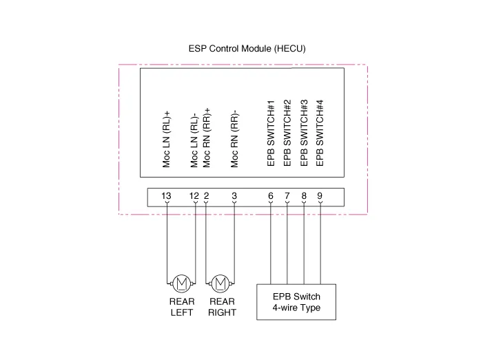
Pin No
|
Fuction
|
Pin No
|
Fuction
|
6
|
Electrical parking brake signal 1
|
2
|
Rear right EPB motor power
|
7
|
Electrical parking brake signal 2
|
3
|
Rear right EPB motor ground
|
8
|
Electrical parking brake signal 3
|
12
|
Rear left EPB motor ground
|
9
|
Electrical parking brake signal 4
|
13
|
Rear left EPB motor power
|
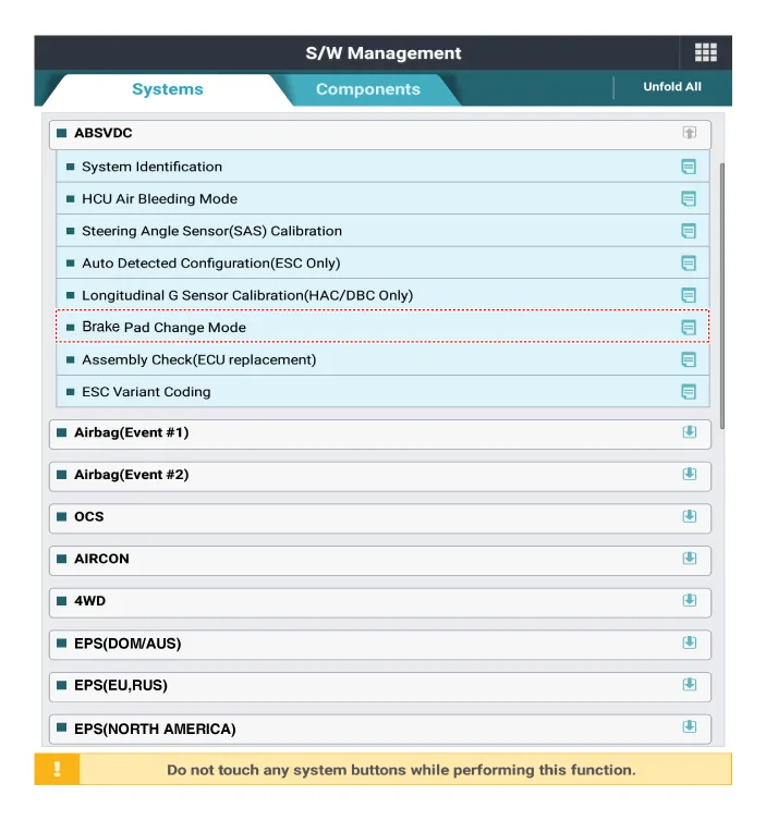
Repair procedures
| Diagnostic procedure by
using diagnostic device |
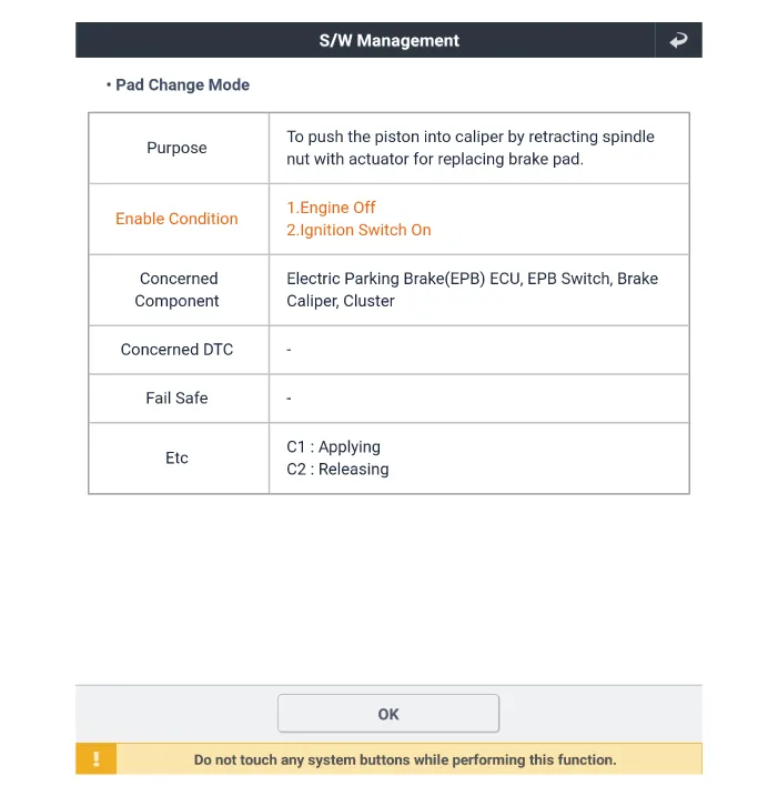
Brake Pad Replacement
Mode
| 1. |
Perform the "Brake Pad Change Mode" using KDS following the procedure
below for vehicles with EPB.
| (1) |
Connect self-diagnosis connector (16pins) located under the driver
side crash pad to self-diagnosis device, and then turn the self-diagnosis
device after key is ON.
|
| (2) |
Select the "vehicle model" and "ABSVDC" on KDS vehicle selection
screen, then select OK.
|
| (3) |
Select the "Brake Pad Change Mode" on KDS screen, then select
OK.
|
| (4) |
Proceed with the test according to the screen instructions.
|
|
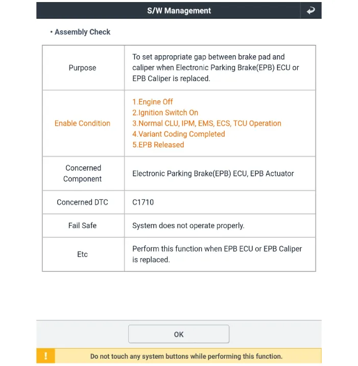
Assembly Check
| 1. |
Perform the "Brake Pad Change Mode" using KDS following the procedure
below for vehicles with EPB.
| (1) |
Connect self-diagnosis connector (16pins) located under the driver
side crash pad to self-diagnosis device, and then turn the self-diagnosis
device after key is ON.
|
| (2) |
Select the "vehicle model" and "ABSVDC" on KDS vehicle selection
screen, then select OK.
|
| (3) |
Select the "Assembly Check" on KDS screen, then select OK.
|
| (4) |
Proceed with the test according to the screen instructions.

|
|
| 1. |
Turn ignition switch off and disconnect the battery (-) cable from the
battery.
|
| 2. |
Remove the floor console upper cover assembly.
(Refer to Body - "Floor Console Assembly")
|
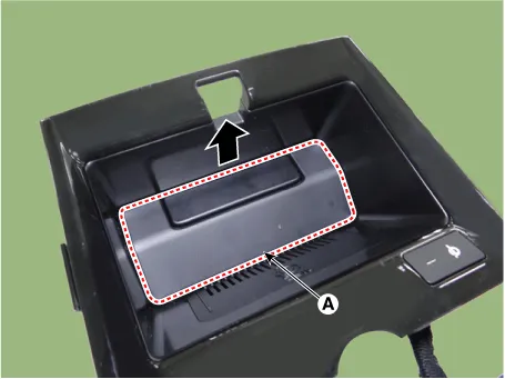
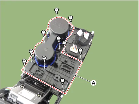
| 3. |
Remove the wireless power charger pad (A).
|
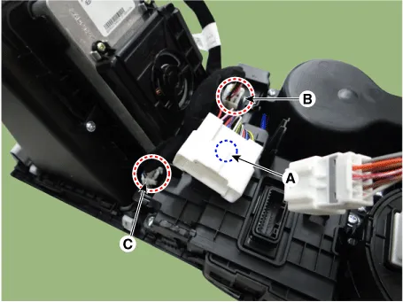
| 4. |
Remove the wireless power charger unit after disconnecting the connector.
(A) : Main connector mounting fasner
(B) : Console floor switch complete connector
(C) : Wireless power charger connector
|
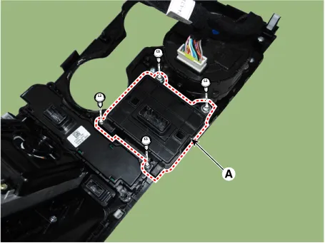
| 5. |
Remove the console cup holder assembly (A) after loosening the screws.
|
| 6. |
Remove the EPB switch (A) after loosening the screws.
|
| 1. |
Turn ignition switch off and disconnect the battery (-) cable from the
battery.
|
| 2. |
Remove the EPB actuator from rear caliper.
(Refer to Brake System - "Rear Brake Caliper")
|
Repair procedures
Removal
1.
Turn ignition switch OFF and disconnect the negative (-) battery cable.
2.
Release the parking brake.
Components and components location
Components
1. ESC control module (HECU)
2. Front wheel speed sensor
3. Rear wheel speed sensor
4.
Other information:
Description and operation
Description
The ambient temperature sensor is located at the front of the condenser and detects
ambient air temperature. It is a negative type thermistor; resistance will increase
with lower temperature, and decrease with higher temperature.
Description and operation
Description
It is installed to the DATC and adjusts the fan rpm by precisely controlling
the voltage applied to the blower motor.
Repair procedures
Inspection
1.
Turn the ignition switch ON.
