Kia Optima DL3: Engine And Transaxle Assembly / Engine Room Under Cover
Repair procedures
| Removal and Installation |
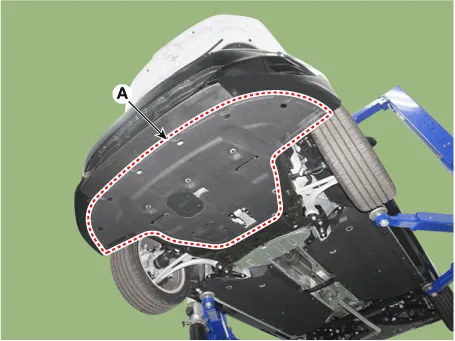
Engine Room Under Cover
| 1. |
Remove the engine room under cover (A).
|
| 2. |
Install in the reverse order of removal. |
Repair procedures Removal and Installation 1. Remove the engine cover (A). • To avoid damage, remove the engine cover on room temperature.
Components and components location Components 1. Transaxle mounting bracket 2. Roll rod bracket 3. Engine mounting bracket 4.
Other information:
Kia Optima DL3 2019-2026 Service and Repair Manual: Power Door Mirror Actuator
Schematic diagrams Connector and Terminal Function Repair procedures Inspection 1. Disconnect the negative battery terminal. 2. Remove the front door trim. (Refer to Body - "Front Door Trim") 3.
Kia Optima DL3 2019-2026 Service and Repair Manual: Smart Key System
Specifications Specifications Smart Key Unit Items Specification Rated voltage DC 12 V Operation voltage DC 9 - 16 V Operation temperature -40 to 185°F (-40 to 85°C) RF Receiver Items
Categories
- Manuals Home
- Kia Optima Owners Manual
- Kia Optima Service Manual
- Instrument panel overview
- Motor Driven Power Steering
- Body Electrical System
- New on site
- Most important about car
