Kia Optima DL3: Engine Control System / ETC (Electronic Throttle Control) System
Specifications
| Specification |
|
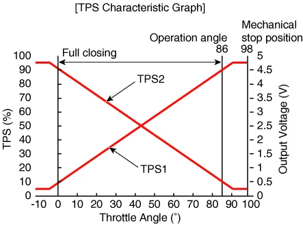
Throttle angle (°) |
Output voltage (V) [Vref = 5.0V] |
|
|
TPS1 |
TPS2 |
|
|
0 |
0.5 |
4.5 |
|
10 |
0.96 |
4.05 |
|
20 |
1.41 |
3.59 |
|
30 |
1.87 |
3.14 |
|
40 |
2.32 |
2.68 |
|
50 |
2.78 |
2.23 |
|
60 |
3.23 |
1.77 |
|
70 |
3.69 |
1.32 |
|
80 |
4.14 |
0.86 |
|
90 |
4.6 |
0.41 |
|
98 |
4.65 |
0.35 |
|
C.T (0) |
0.5 |
4.5 |
|
W.O.T (86) |
4.41 |
0.59 |
[ETC Motor]
|
Item |
Specification |
|
Coil Resistance (Ω) |
0.3 - 100 [20°C(68°F)] |
Description and operation
| Description |
| • |
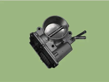
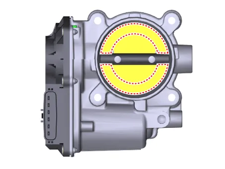
The Electronic Throttle Control (ETC) System consists of a throttle body with an integrated control motor and Throttle Position Sensor (TPS). |
| • |
Instead of the traditional throttle cable, an Accelerator Position Sensor (APS) is used to receive driver input. |
| • |
The ECM uses the APS signal to calculate the target throttle angle; the position of the throttle is then adjusted via ECM control of the ETC motor. |
| • |
The TPS signal is used to provide feedback regarding throttle position to the ECM. |
| • |
Using ETC, precise control over throttle position is possible; the need for external cruise control modules/cables is eliminated. |
Components and components location
| Components Location |
| 1. ETC (Electronic Throttle Control)
|
Schematic diagrams
| Circuit Diagram |
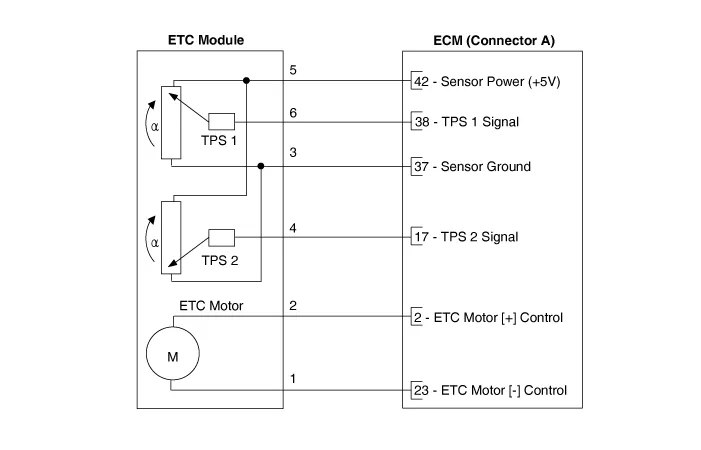
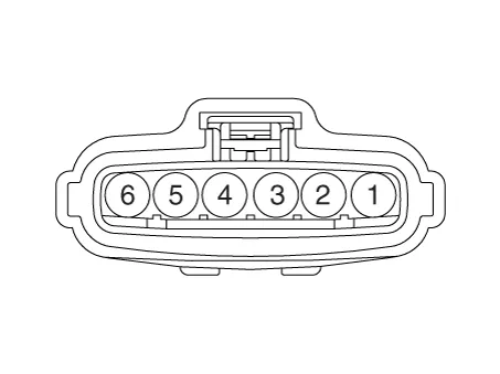
Harness Connector
Repair procedures
| Inspection |
| 1. |
The engine control system can be more quickly diagnosed for troubles by using the vehicle diagnostic system (KDS). (Refer to "DTC guide") KDS provides the following information.
|
Throttle Position Sensor (TPS)
| 1. |
Connect the KDS on the Data Link Connector (DLC). |
| 2. |
Start the engine and measure the output voltage of TPS 1 and 2 at C.T. and W.O.T.
|
||||||||||||||||||||||||||||||||||||||||||||
ETC Motor
| 1. |
Disconnect the ETC module connector. |
| 2. |
Measure resistance between the ETC module terminals 1 and 2.
|
| Removal |
| 1. |
Disconnect the negative battery terminal. |
| 2. |
Remove the air cleaner. (Refer to Engine Mechanical System - "Air Cleaner") |
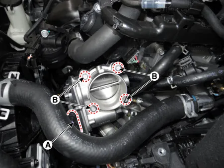
| 3. |
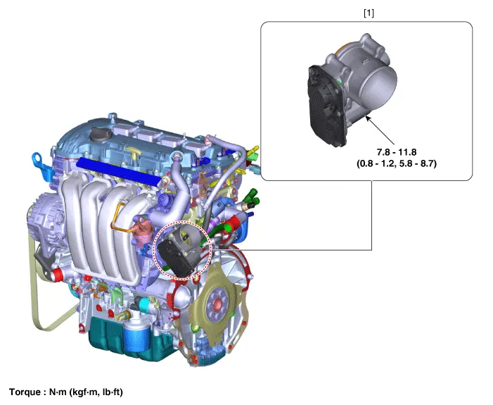
After disconnecting the connector (A), remove the ETC module by loosening the bolts (B).
|
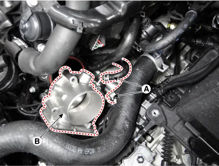
| 4. |
Separate the coolant hoses (A) from the ETC module (B).
|
| Installation |
|

| 1. |
Install in the reverse order of removal. |
| 2. |
Supplement the engine coolant. (Refer to Engine Mechanical System - "Coolant") |
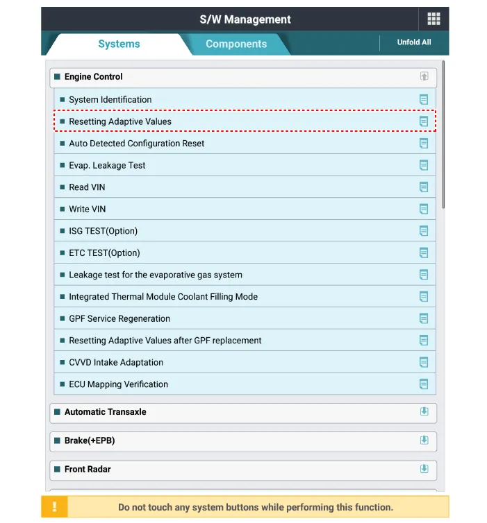
| 3. |
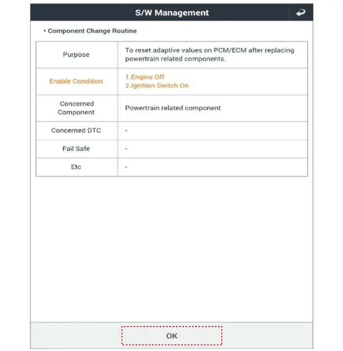
Reset the ECM adaptive values after replacing the ETC.
|
| 4. |
Perform the ETC learning procedure. (Refer to ETC (Electronic Throttle Control) System - "Adjustment") |
| Adjustment |
|
| 1. |
Wait for 1 minute with the ignition switch ON. |
| 2. |
Start the engine and hold the idle status for 15 minutes. |
| 3. |
Waif for 1 minute with the ignition switch OFF. |
| 4. |
Restart the engine, check that the idle speed is stable. |
| Cleaning |
| 1. |
Remove the ETC. (Refer to ETC - "Removal")
|
| 2. |
Clean the pollutant in the throttle body using a soft cloth moistened with cleaning fluid.
|
| 3. |
Install the ETC. (Refer to ETC - "Installation") |
| 4. |
Reset the ETC adaptive value.
|
| 5. |
Perform the ETC learning procedure. (Refer to ETC - "Adjustment") |
Troubleshooting
| Fail-Safe Mode |
|
Item |
Fail-Safe |
|
|
ETC Motor |
Throttle valve stuck at 7° |
|
|
TPS |
TPS 1 fault |
Replace it with TPS 2 |
|
TPS 2 fault |
Replace it with TPS 1 |
|
|
TPS 1,2 fault |
Throttle valve stuck at 7° |
|
|
APS |
APS 1 fault |
Replace it with APS 2 |
|
APS 2 fault |
Replace it with APS 1 |
|
|
APS 1,2 fault |
Engine idle state |
|
When throttle value is stuck at 7°, engine speed is limited at below 1,500rpm and vehicle speed at maximum 40 - 50 km/h (25 - 31 mph) |
Components and components location Component Location 1. Engine Control Module (ECM) Schematic diagrams Connector and Terminal function ECM Terminal Function [Connector A] Pin Function Connected to 1 - 2 ETC Motor [+] control output ETC Motor 3 - 4 - 5 - 6 - 7 - 8 - 9 - 10 - 11 - 12 - 13 - 14 - 15 Sensor ground Engine Coolant Temperature Sensor (ECTS) 16 Engine Coolant Temperature Sensor (ECTS) signal input Engine Coolant Temperature Sensor (ECTS) 17 Throttle Position Sensor (TPS) 2 signal input Throttle Position Sensor (TPS) 2 [ETC Module] 18 - 19 - 20 - 21 Sensor power (+5V) Manifold Absolute Pressure Sensor (MAPS) Camshaft Position Sensor (CMPS) [Bank 1 / Intake] 22 - 23 ETC Motor [-] control output ETC Motor [ETC Module] 24 - 25 - 26 - 27 - 28 - 29 - 30 - 31 Electrical load signal input (FR) Alternator 32 - 33 - 34 - 35 - 36 - 37 Sensor ground Throttle Position Sensor (TPS) 1, 2 [ETC Module] 38 Throttle Position Sensor (TPS) 1 signal input Throttle Position Sensor (TPS) 1 [ETC Module] 39 - 40 Alternator PWM control output Alternator 41 - 42 Sensor power (+5V) Throttle Position Sensor (TPS) 1, 2 [ETC Module] 43 - 44 - 45 - 46 - 47 - 48 - 49 - 50 - 51 - 52 - 53 - 54 - 55 - 56 Sensor ground Camshaft Position Sensor (CMPS) [Bank 1/Exhaust] 57 - 58 - 59 - 60 - 61 Sensor ground Manifold Absolute Pressure Sensor (MAPS) 62 Manifold Absolute Pressure Sensor (MAPS) signal input Manifold Absolute Pressure Sensor (MAPS) 63 Sensor power (+5V) Camshaft Position Sensor (CMPS) [Bank 1 / Exhaust] 65 - 66 - 67 - 68 - 69 - 70 - 71 - 72 - 73 - 74 Sensor ground Crankshaft Position Sensor (CKPS) 75 - 76 - 77 Camshaft Position Sensor (CMPS) [Bank 1 / Exhaust] signal input Camshaft Position Sensor (CMPS) [Bank 1 / Exhaust] 78 Sensor ground Camshaft Position Sensor (CMPS) [Bank 1 / Intake] 79 - 80 - 81 - 82 - 83 VG (Virtual Ground) Heated Oxygen Sensor [Bank 1 / Sensor 1] 84 VRC (Current Adjust) Heated Oxygen Sensor [Bank 1 / Sensor 1] 85 - 86 - 87 - 88 - 89 - 90 - 91 - 92 - 93 - 94 - 95 Crankshaft Position Sensor (CKPS) signal input Crankshaft Position Sensor (CKPS) 96 - 97 - 98 Camshaft Position Sensor (CMPS) [Bank 1 / Intake] signal input Camshaft Position Sensor (CMPS) [Bank 1 / Intake] 99 Sensor ground Knock Sensor (KS) 100 Knock Sensor (KS) signal input Knock Sensor (KS) 101 Intake Air Temperature Sensor (IATS) signal input Intake Air Temperature Sensor (IATS) 102 - 103 - 104 VN (NERNST Cell Voltage) Heated Oxygen Sensor (HO2S) [Bank 1 / Sensor 1] 105 VIP (Current Pump) Heated Oxygen Sensor [Bank 1 / Sensor 1] [Connector B] Pin Function Connected to 1 Power ground Chassis Ground 2 Power ground Chassis Ground 3 Battery power (B+) Main Relay 4 Power ground Chassis Ground 5 Battery power (B+) Main Relay 6 Battery power (B+) Main Relay 7 - 8 - 9 - 10 Accelerator Position Sensor (APS) 2 signal input Accelerator Position Sensor (APS) 2 11 A/C Pressure Transducer (APT) signal input A/C Pressure Transducer (APT) 12 - 13 - 14 Sensor power (+5V) A/C Pressure Transducer (APT) 15 - 16 Sensor power (+5V) Accelerator Position Sensor (APS) 2 17 Sensor power (+5V) Accelerator Position Sensor (APS) 1 18 Main Relay control output Main Relay 19 Fuel Pump Relay control output Fuel Pump Relay 20 - 21 - 22 Injector (Cylinder #2) control output Injector (Cylinder #3) 23 Injector (Cylinder #3) control output Injector (Cylinder #3) 24 - 25 - 26 - 27 Accelerator Position Sensor (APS) 1 signal input Accelerator Position Sensor (APS) 1 28 Sensor ground Heated Oxygen Sensor (HO2S) [Bank 1 / Sensor 2] 29 Heated Oxygen Sensor (HO2S) [Bank 1 / Sensor 2] signal input Heated Oxygen Sensor (HO2S) [Bank 1 / Sensor 2] 30 - 31 - 32 - 33 - 34 Start Motor relay control output Start Motor relay 35 CVVT Oil Control (OCV) Valve [Bank 1 / Exhaust] control output CVVT Oil Control Valve (OCV) [Bank 1 / Exhaust] 36 CVVT Oil Control (OCV) Valve [Bank 1 / Intake] control output CVVT Oil Control Valve (OCV) [Bank 1 / Intake] 37 - 38 A/C Relay control output A/C Relay 39 Injector (Cylinder #4) control output Injector (Cylinder #3) 40 Ignition Coil (Cylinder #2) control output Ignition Coil (Cylinder #2) 41 Battery power (B+) Ignition Switch 42 - 43 - 44 - 45 Sensor ground Accelerator Position Sensor (APS) 1 46 Sensor ground Accelerator Position Sensor (APS) 2 47 - 48 - 49 - 50 Sensor ground A/C Pressure Transducer (APT) 51 - 52 - 53 - 54 - 55 - 56 Injector (Cylinder #1) control output Injector (Cylinder #1) 57 Ignition Coil (Cylinder #4) control output Ignition Coil (Cylinder #4) 58 - 59 LOCAL-CAN [Low] Other control module, Data Link Connector (DLC) 60 P-CAN [Low] Other control module, Data Link Connector (DLC) 61 Fuel Tank Level Sensor signal input Fuel Tank Level Sensor (FLS) 62 - 63 - 64 - 65 Brake Light Switch signal input Brake Switch 66 Start signal input Ignition Switch 67 Engine speed signal output Power Distribution Module (PDM) 68 Immobilizer communication line Immobilizer control module 69 - 70 - 71 Purge Control Solenoid Valve (PCSV) control output Purge Control Solenoid Valve (PCSV) 72 - 73 Heated Oxygen Sensor (HO2S) [Bank 1 / Sensor 1] Heater control output Heated Oxygen Sensor (HO2S) [Bank 1 / Sensor 1] 74 Ignition Coil (Cylinder #3) control output Ignition Coil (Cylinder #3) 75 Memory power (B+) Engine Room Fuse & Relay Box (EMS ECU) 76 LOCAL-CAN [High] Other control module, Data Link Connector (DLC) 77 C-CAN [High] Other control module, Data Link Connector (DLC) 78 - 79 Vehicle speed signal input ABS/ESC Control Unit 80 - 81 Wiper Switch Input Signal Integrated Body Control Unit (IBU) 82 - 83 Brake Test Switch signal input Brake Switch 84 - 85 - 86 Cooling Fan Relay control output Cooling Fan Relay 87 - 88 Variable Intake Solenoid (VIS) Valve control output Variable Intake Solenoid (VIS) Valve 89 - 90 Heated Oxygen Sensor (HO2S) [Bank 1 / Sensor 2] Heater control output Heated Oxygen Sensor (HO2S) [Bank 1 / Sensor 2] 91 Ignition Coil (Cylinder #1) control output Ignition Coil (Cylinder #1) [NON-Immobilizer type] Repair procedures Inspection 1.
Specifications Specification Manifold Absolute Pressure Sensor (MAPS) Pressure Output Voltage (V) kPa kgf/cm² psi 20 0.
Other information:
Kia Optima DL3 2019-2026 Service and Repair Manual: Hazard Lamp Switch
Schematic diagrams Connector and Terminal Function Repair procedures Removal 1. Disconnect the negative battery terminal. 2. Remove the crash pad garnish [RH]. (Refer to Body - "Crash Pad Garnish") 3.
Kia Optima DL3 2019-2026 Service and Repair Manual: Room Lamp
Repair procedures Removal When removing with a flat-tip screwdriver or remover, wrap protective tape around the tools to prevent damage to components. 1.
Categories
- Manuals Home
- Kia Optima Owners Manual
- Kia Optima Service Manual
- Identification Numbers
- Rear Brake Disc
- Automatic Transaxle System
- New on site
- Most important about car
