Kia Optima DL3: Engine Control / Fuel System / Engine Control System
Description and operation
| Description |
If the Gasoline Engine Control system components (sensors, ECM, injector, etc.) fail, interruption to the fuel supply or failure to supply the proper amount of fuel for various engine operating conditions will result. The following situations may be encountered.
| 1. |
Engine is hard to start or does not start at all. |
| 2. |
Unstable idle. |
| 3. |
Poor driveability |
If any of the above conditions are noted, first perform a routine diagnosis that includes basic engine checks (ignition system malfunction, incorrect engine adjustment, etc.). Then, inspect the Gasoline Engine Control system components with the KDS.
|

Malfunction Indicator Lamp (MIL)
[EOBD]
A malfunction indicator lamp illuminates to notify the driver that there is a problem with the vehicle. However, the MIL will go off automatically after 3 subsequent sequential driving cycles without the same malfunction. Immediately after the ignition switch is turned on (ON position - do not start), the MIL will illuminate continuously to indicate that the MIL operates normally.
Faults with the following items will illuminate the MIL.
| • |
Catalyst |
| • |
Fuel system |
| • |
Air Flow Sensor |
| • |
Intake Air Temperature Sensor |
| • |
Engine Coolant Temperature Sensor |
| • |
Throttle Position Sensor |
| • |
Heated Oxygen Sensor (Upstream) |
| • |
Heated Oxygen Sensor Heater (Upstream) |
| • |
Heated Oxygen Sensor (Downstream) |
| • |
Heated Oxygen Sensor Heater (Downstream) |
| • |
Injector |
| • |
Misfire |
| • |
Crankshaft Position Sensor |
| • |
Camshaft Position Sensor |
| • |
Evaporative Emission Control System |
| • |
Vehicle Speed Sensor |
| • |
Idle Speed Control System |
| • |
Power Supply |
| • |
ECM/ PCM |
| • |
MT/AT Encoding |
| • |
Acceleration Sensor |
| • |
MIL-ON Request Signal |
| • |
Power Stage |
|
[NON-EOBD]
A malfunction indicator lamp illuminates to notify the driver that there is a problem with the vehicle. However, the MIL will go off automatically after 3 subsequent sequential driving cycles without the same malfunction. Immediately after the ignition switch is turned on (ON position - do not start), the MIL will illuminate continuously to indicate that the MIL operates normally.
Faults with the following items will illuminate the MIL
| • |
Heated Oxygen Sensor (HO2S) |
| • |
Mass Air Flow sensor (MAFS) |
| • |
Throttle Position Sensor (TPS) |
| • |
Engine Coolant Temperature Sensor (ECTS) |
| • |
Idle Speed Control Actuator (ISCA) |
| • |
Injectors |
| • |
ECM |
|
[INSPECTION]
| 1. |
After turning ON the ignition key, ensure that the light illuminates for about 5 seconds and then goes out. |
| 2. |
If the light does not illuminate, check for an open circuit in the harness, a blown fuse or a blown bulb. |
Self-Diagnosis
The ECM monitors the input/output signals (some signals at all times and the others under specified conditions). When the ECM detects an irregularity, it records the diagnostic trouble code, and outputs the signal to the Data Link connector. The diagnosis results can be read with the MIL or the KDS. Diagnostic Trouble Codes (DTC) will remain in the ECM as long as battery power is maintained. The diagnostic trouble codes will, however, be erased when the battery terminal or ECM connector is disconnected, or by the KDS.
|
The relation between DTC and driving pattern in EOBD system
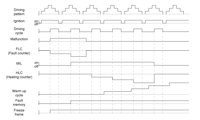
| 1. |
When the same malfunction is detected and maintained during two sequential driving cycles, the MIL will automatically illuminate. |
| 2. |
The MIL will go off automatically if no fault is detected after 3 sequential driving cycles. |
| 3. |
A Diagnostic Trouble Code(DTC) is recorded in ECM memory when a malfunction is detected after two sequential driving cycles. The MIL will illuminate when the malfunction is detected on the second driving cycle. If a misfire is detected, a DTC will be recorded, and the MIL will illuminate, immediately after a fault is first detected. |
| 4. |
A Diagnostic Trouble Code(DTC) will automatically erase from ECM memory if the same malfunction is not detected for 40 driving cycles.
|
- Engine Control Module (ECM)
- ETC (Electronic Throttle Control) System
- Manifold Absolute Pressure Sensor (MAPS) & Intake Air Temperature Sensor (IATS)
- Engine Coolant Temperature Sensor (ECTS)
- Crankshaft Position Sensor (CKPS)
- Camshaft Position Sensor (CMPS)
- Knock Sensor (KS)
- Heated Oxygen Sensor (HO2S)
- Accelerator Position Sensor (APS)
- CVVT Oil Control Valve (OCV)
- Variable Intake Solenoid (VIS) Valve
- Variable Charge Motion Actuator (VCMA)
Service data Service Data Sensor Manifold Absolute Pressure Sensor (MAPS) Pressure Output Voltage (V) kPa kgf/cm² psi 20 0.
Components and components location Component Location 1. Engine Control Module (ECM) Schematic diagrams Connector and Terminal function ECM Terminal Function [Connector A] Pin Function Connected to 1 - 2 ETC Motor [+] control output ETC Motor 3 - 4 - 5 - 6 - 7 - 8 - 9 - 10 - 11 - 12 - 13 - 14 - 15 Sensor ground Engine Coolant Temperature Sensor (ECTS) 16 Engine Coolant Temperature Sensor (ECTS) signal input Engine Coolant Temperature Sensor (ECTS) 17 Throttle Position Sensor (TPS) 2 signal input Throttle Position Sensor (TPS) 2 [ETC Module] 18 - 19 - 20 - 21 Sensor power (+5V) Manifold Absolute Pressure Sensor (MAPS) Camshaft Position Sensor (CMPS) [Bank 1 / Intake] 22 - 23 ETC Motor [-] control output ETC Motor [ETC Module] 24 - 25 - 26 - 27 - 28 - 29 - 30 - 31 Electrical load signal input (FR) Alternator 32 - 33 - 34 - 35 - 36 - 37 Sensor ground Throttle Position Sensor (TPS) 1, 2 [ETC Module] 38 Throttle Position Sensor (TPS) 1 signal input Throttle Position Sensor (TPS) 1 [ETC Module] 39 - 40 Alternator PWM control output Alternator 41 - 42 Sensor power (+5V) Throttle Position Sensor (TPS) 1, 2 [ETC Module] 43 - 44 - 45 - 46 - 47 - 48 - 49 - 50 - 51 - 52 - 53 - 54 - 55 - 56 Sensor ground Camshaft Position Sensor (CMPS) [Bank 1/Exhaust] 57 - 58 - 59 - 60 - 61 Sensor ground Manifold Absolute Pressure Sensor (MAPS) 62 Manifold Absolute Pressure Sensor (MAPS) signal input Manifold Absolute Pressure Sensor (MAPS) 63 Sensor power (+5V) Camshaft Position Sensor (CMPS) [Bank 1 / Exhaust] 65 - 66 - 67 - 68 - 69 - 70 - 71 - 72 - 73 - 74 Sensor ground Crankshaft Position Sensor (CKPS) 75 - 76 - 77 Camshaft Position Sensor (CMPS) [Bank 1 / Exhaust] signal input Camshaft Position Sensor (CMPS) [Bank 1 / Exhaust] 78 Sensor ground Camshaft Position Sensor (CMPS) [Bank 1 / Intake] 79 - 80 - 81 - 82 - 83 VG (Virtual Ground) Heated Oxygen Sensor [Bank 1 / Sensor 1] 84 VRC (Current Adjust) Heated Oxygen Sensor [Bank 1 / Sensor 1] 85 - 86 - 87 - 88 - 89 - 90 - 91 - 92 - 93 - 94 - 95 Crankshaft Position Sensor (CKPS) signal input Crankshaft Position Sensor (CKPS) 96 - 97 - 98 Camshaft Position Sensor (CMPS) [Bank 1 / Intake] signal input Camshaft Position Sensor (CMPS) [Bank 1 / Intake] 99 Sensor ground Knock Sensor (KS) 100 Knock Sensor (KS) signal input Knock Sensor (KS) 101 Intake Air Temperature Sensor (IATS) signal input Intake Air Temperature Sensor (IATS) 102 - 103 - 104 VN (NERNST Cell Voltage) Heated Oxygen Sensor (HO2S) [Bank 1 / Sensor 1] 105 VIP (Current Pump) Heated Oxygen Sensor [Bank 1 / Sensor 1] [Connector B] Pin Function Connected to 1 Power ground Chassis Ground 2 Power ground Chassis Ground 3 Battery power (B+) Main Relay 4 Power ground Chassis Ground 5 Battery power (B+) Main Relay 6 Battery power (B+) Main Relay 7 - 8 - 9 - 10 Accelerator Position Sensor (APS) 2 signal input Accelerator Position Sensor (APS) 2 11 A/C Pressure Transducer (APT) signal input A/C Pressure Transducer (APT) 12 - 13 - 14 Sensor power (+5V) A/C Pressure Transducer (APT) 15 - 16 Sensor power (+5V) Accelerator Position Sensor (APS) 2 17 Sensor power (+5V) Accelerator Position Sensor (APS) 1 18 Main Relay control output Main Relay 19 Fuel Pump Relay control output Fuel Pump Relay 20 - 21 - 22 Injector (Cylinder #2) control output Injector (Cylinder #3) 23 Injector (Cylinder #3) control output Injector (Cylinder #3) 24 - 25 - 26 - 27 Accelerator Position Sensor (APS) 1 signal input Accelerator Position Sensor (APS) 1 28 Sensor ground Heated Oxygen Sensor (HO2S) [Bank 1 / Sensor 2] 29 Heated Oxygen Sensor (HO2S) [Bank 1 / Sensor 2] signal input Heated Oxygen Sensor (HO2S) [Bank 1 / Sensor 2] 30 - 31 - 32 - 33 - 34 Start Motor relay control output Start Motor relay 35 CVVT Oil Control (OCV) Valve [Bank 1 / Exhaust] control output CVVT Oil Control Valve (OCV) [Bank 1 / Exhaust] 36 CVVT Oil Control (OCV) Valve [Bank 1 / Intake] control output CVVT Oil Control Valve (OCV) [Bank 1 / Intake] 37 - 38 A/C Relay control output A/C Relay 39 Injector (Cylinder #4) control output Injector (Cylinder #3) 40 Ignition Coil (Cylinder #2) control output Ignition Coil (Cylinder #2) 41 Battery power (B+) Ignition Switch 42 - 43 - 44 - 45 Sensor ground Accelerator Position Sensor (APS) 1 46 Sensor ground Accelerator Position Sensor (APS) 2 47 - 48 - 49 - 50 Sensor ground A/C Pressure Transducer (APT) 51 - 52 - 53 - 54 - 55 - 56 Injector (Cylinder #1) control output Injector (Cylinder #1) 57 Ignition Coil (Cylinder #4) control output Ignition Coil (Cylinder #4) 58 - 59 LOCAL-CAN [Low] Other control module, Data Link Connector (DLC) 60 P-CAN [Low] Other control module, Data Link Connector (DLC) 61 Fuel Tank Level Sensor signal input Fuel Tank Level Sensor (FLS) 62 - 63 - 64 - 65 Brake Light Switch signal input Brake Switch 66 Start signal input Ignition Switch 67 Engine speed signal output Power Distribution Module (PDM) 68 Immobilizer communication line Immobilizer control module 69 - 70 - 71 Purge Control Solenoid Valve (PCSV) control output Purge Control Solenoid Valve (PCSV) 72 - 73 Heated Oxygen Sensor (HO2S) [Bank 1 / Sensor 1] Heater control output Heated Oxygen Sensor (HO2S) [Bank 1 / Sensor 1] 74 Ignition Coil (Cylinder #3) control output Ignition Coil (Cylinder #3) 75 Memory power (B+) Engine Room Fuse & Relay Box (EMS ECU) 76 LOCAL-CAN [High] Other control module, Data Link Connector (DLC) 77 C-CAN [High] Other control module, Data Link Connector (DLC) 78 - 79 Vehicle speed signal input ABS/ESC Control Unit 80 - 81 Wiper Switch Input Signal Integrated Body Control Unit (IBU) 82 - 83 Brake Test Switch signal input Brake Switch 84 - 85 - 86 Cooling Fan Relay control output Cooling Fan Relay 87 - 88 Variable Intake Solenoid (VIS) Valve control output Variable Intake Solenoid (VIS) Valve 89 - 90 Heated Oxygen Sensor (HO2S) [Bank 1 / Sensor 2] Heater control output Heated Oxygen Sensor (HO2S) [Bank 1 / Sensor 2] 91 Ignition Coil (Cylinder #1) control output Ignition Coil (Cylinder #1) [NON-Immobilizer type] Repair procedures Inspection 1.
Other information:
Kia Optima DL3 2019-2026 Service and Repair Manual: Wiper Arm
Repair procedures Removal 1. If necessary, remove the blade by pushing it in the direction arrow after opening the hook (A). • Move the windshield glass wiper blades to the servic
Kia Optima DL3 2019-2026 Service and Repair Manual: Heater Unit
Components and components location Component Location 1. Heater unit assembly Compoents 1. Mode control actuator 2. Temperature control actuator [LH] 3. PTC Heater dummy 4.
Categories
- Manuals Home
- Kia Optima Owners Manual
- Kia Optima Service Manual
- Heating, Ventilation and Air Conditioning
- Body Electrical System
- Charging System
- New on site
- Most important about car
