
Kia Optima DL3: Audio/AVN System / Antenna
Components and components location
| Components Location |
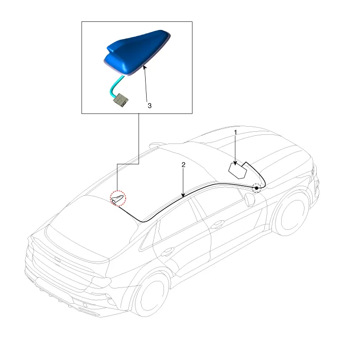
| 1. Audio/AVN head unit 2. Antenna feeder cable |
3. Roof antenna |
Repair procedures
| Removal |
| 1. |
Disconnect the negative battery terminal. |
| 2. |
Remove the roof trim assembly. (Refer to Body - "Roof Trim Assembly") |
| 3. |
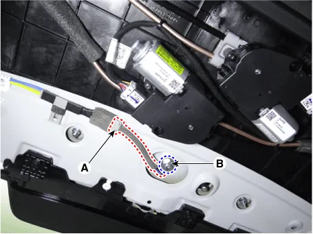
Disconnect the roof antenna connector (A). |
| 4. |
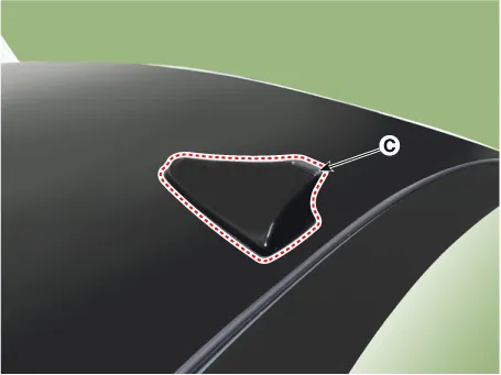
Remove the roof antenna (C) by loosening the mounting nut (B).
|
| Installation |
| 1. |
Install in the reverse order of removal. |
Components and components location Component Location 1. External amp Schematic diagrams Connector and Terminal Function Pin Function Connector A Connector B 1 Battery (+) Right front door tweeter speaker (+) 2 Battery (+) Left front door tweeter speaker (+) 3 Battery (+) Sub woofer speaker (+) 4 Battery (+) - 5 - - 6 MM-CAN (High) - 7 MM-CAN (Low) Amplifier navigation voice (+) 8 ACC - 9 - - 10 - - 11 - - 12 Right surround speaker (+) Right rear door speaker (+) 13 Left surround speaker (+) Left rear door speaker (+) 14 Right midrange speaker (+) Center speaker(+) 15 Left midrange speaker (+) - 16 Ground Right front door tweeter speaker (-) 17 Ground Left front door tweeter speaker (-) 18 Ground Sub woofer speaker (-) 19 Ground - 20 Amplifier SPDIF (High) - 21 Amplifier SPDIF (Low) Amplifier navigation voice (-) 22 Amplifier SPDIF (Ground) - 23 - - 24 IGN1 - 25 Right surround speaker (-) Right rear door speaker (-) 26 Left surround speaker (-) Left rear door speaker (-) 27 Right midrange speaker (-) Center speaker (-) 28 Left midrange speaker (-) - Repair procedures Inspection • Warning and guide sounds regarding engine start and driving are generated by the external amplifier.
Components and components location Components 1. Left remote control switch (Audio + Bluetooth + Voice) 2. Right remote control switch (Trip + SCC + LFA) Schematic diagrams Circuit Diagram [Audio + Bluetooth + Voice] [Trip + SCC + LFA] Repair procedures Removal 1.
Other information:
Kia Optima DL3 2019-2026 Service and Repair Manual: High Mounted Stop Lamp
Repair procedures Removal 1. Disconnect the negative battery terminal. 2. Remove the roof trim assembly. (Refer to Body - "Roof Trim Assembly") 3. Disconnect the high mounted stop lamp connector (A).
Kia Optima DL3 2019-2026 Service and Repair Manual: Power Door Lock Switch
Repair procedures Inspection Power Window Main Switch Diagnosis With KDS 1. In the body electrical system, failure can be quickly diagnosed by using the vehicle diagnostic system (KDS). The diagnostic system (KDS) provides the following information.
Categories
- Manuals Home
- Kia Optima Owners Manual
- Kia Optima Service Manual
- Headlamps
- Automatic Transaxle System
- Motor Driven Power Steering
- New on site
- Most important about car
