Kia Optima DL3: Front View Camera System / Front View Camera Unit
Schematic diagrams
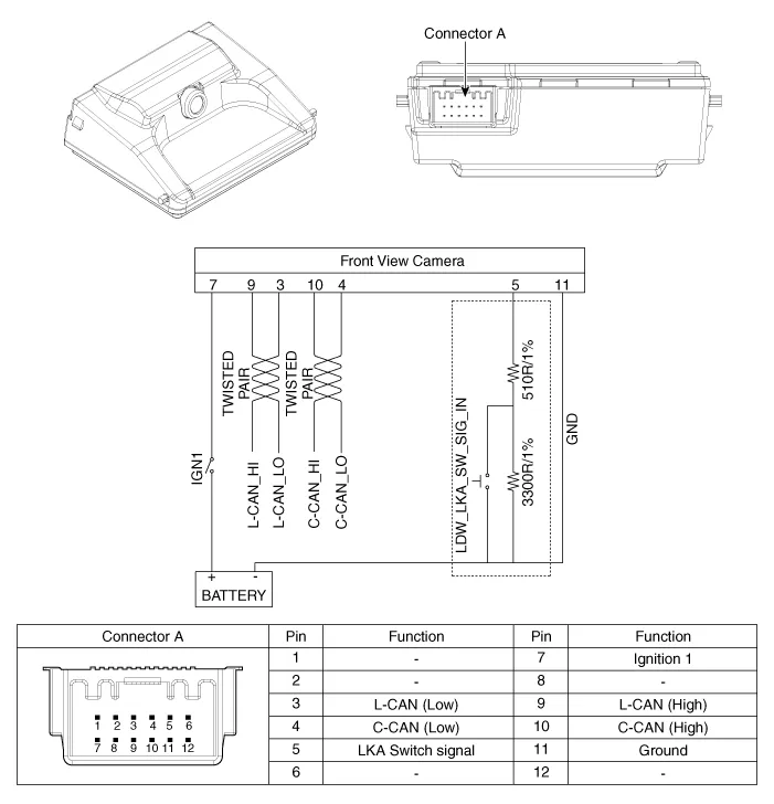
| Circuit Diagram |
Repair procedures
| Inspection |
| 1. |
In the body electrical system, failure can be quickly diagnosed by using Kia Diagnostic System (KDS). The diagnostic system (KDS) provides the following information.
|
| Removal |
| 1. |
You should read the specification information for the front view camera that is installed in the vehicle before replacing it with a new front view camera.
|
| 2. |
Disconnect the negative (-) battery terminal. |
| 3. |
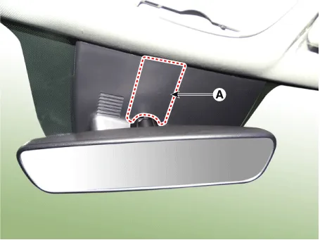
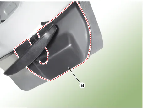
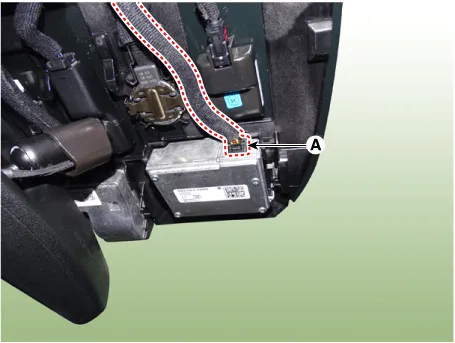
Remove the inside rear view mirror cover (A) and unit cover (B).
|
| 4. |
Disconnect the front view camera connector (A).
|
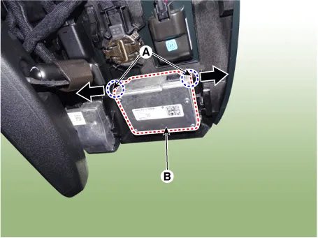
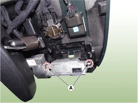
| 5. |
Separate the fixed points (A) of coupler, remove the front view camera (B).
|

| Installation |
| 1. |
Install in the reverse order of removal.
|
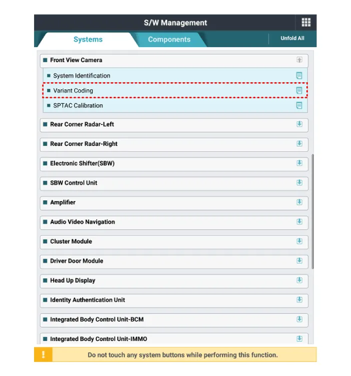
| 2. |
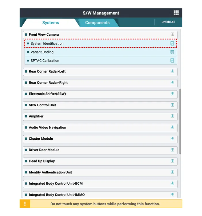
When replacing the front view camera with a new one, perform the "Variant Coding" procedure using KDS.
|
| 3. |
Perform the front view camera unit calibration. (Refer to Front View Camera Unit - "Adjustment") |
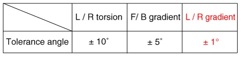
| Adjustment |
Perform the camera calibration in the following case.
Check the procedure below before performing the camera calibration.
|
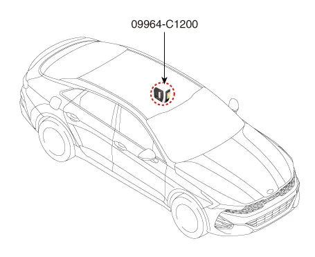
Service Point Target Auto Calibration (SPTAC) Procedure
| 1. |
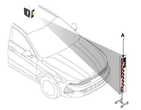
Install the SST (09964-C1200) on the roof center above the vehicle's front windshield.
|
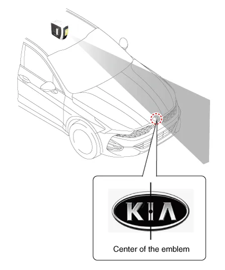
| 2. |
Have the laser illuminate starting from the roof center and to passing through the center of the emblem.
|

| 3. |
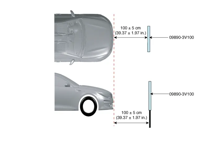
Place the calibration target (09890-3V100) so that it adheres by 0 cm to the bumper front. [max. tolerance: 5 cm (1.97 in.)]
|

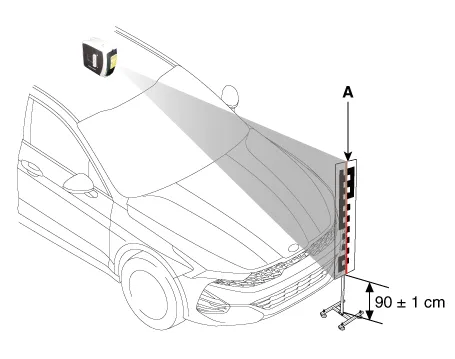
| 4. |
Set the calibration target height to 90 ± 1 cm (35.43 ± 0.39 in.) from the ground and align the center of calibration target with center line (A) of laser beam. The target is placed along the vehicle’s longitudinal axis (centerline) within ± 3cm (± 1.18 inch) of target center.
|

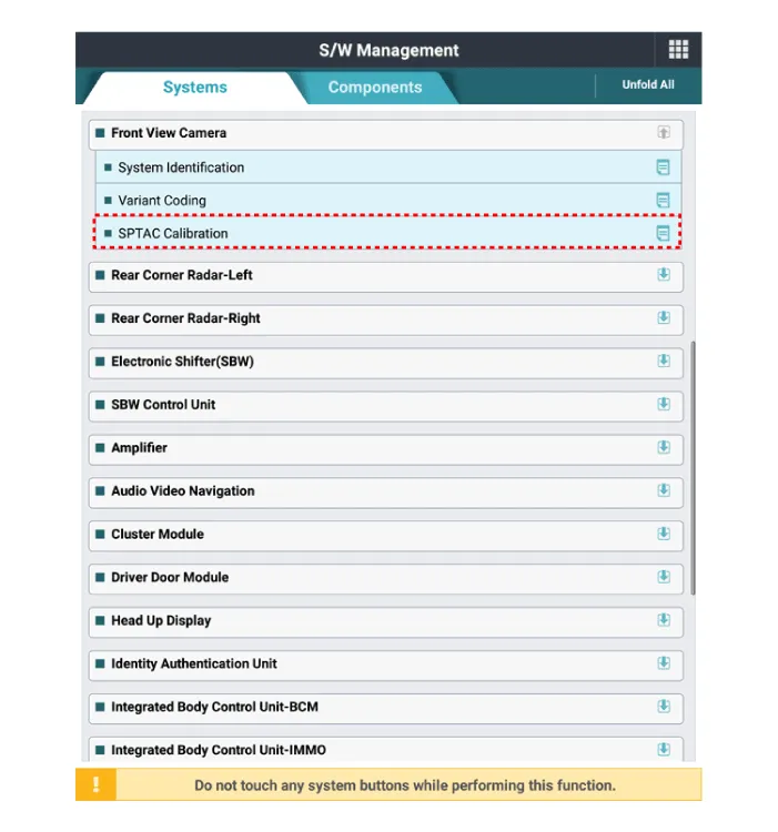
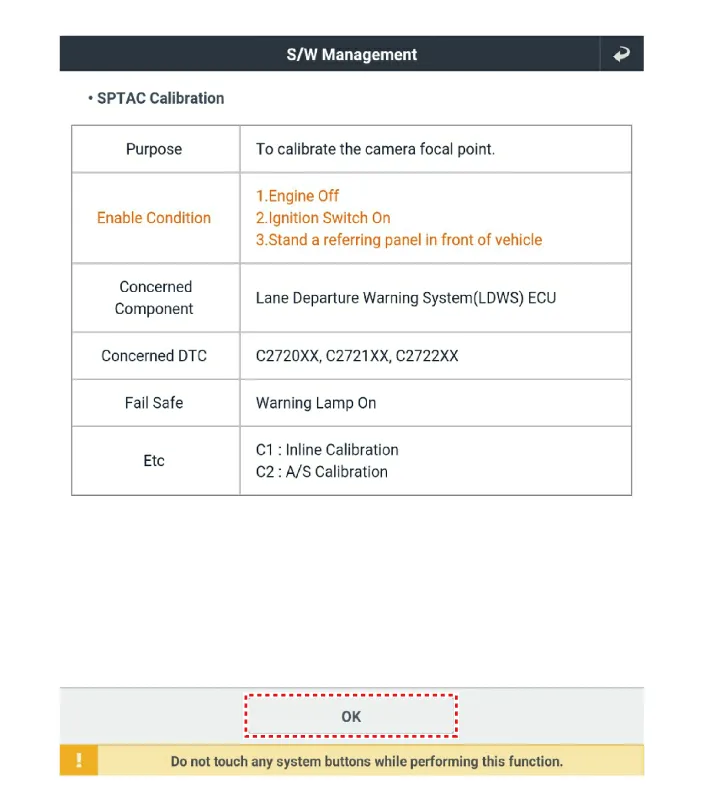
| 5. |
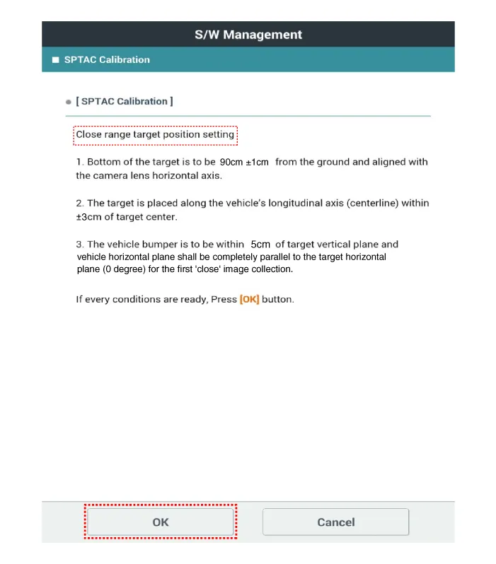
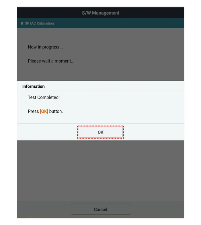
Perform the "SPTAC Calibration" using the KDS.
|
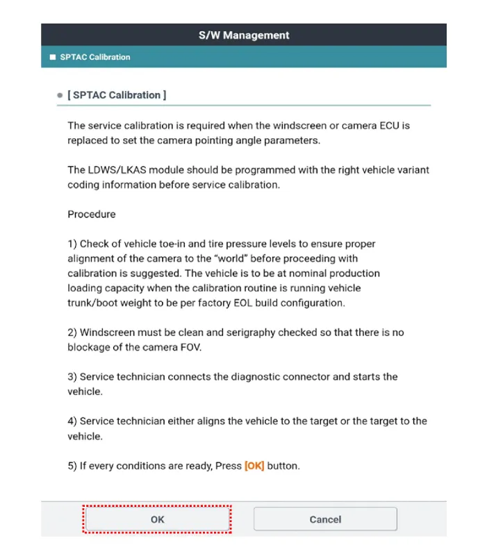
| 6. |
Perform the short-distance calibration by selecting the "OK" message on the KDS after checking the calibration target location.
|

| 7. |
Move the calibration target (09890-3V100) at 100 cm (39.37 in.) from the bumper. [max. tolerance : ± 5 cm (± 1.97 in.)]
|
| 8. |
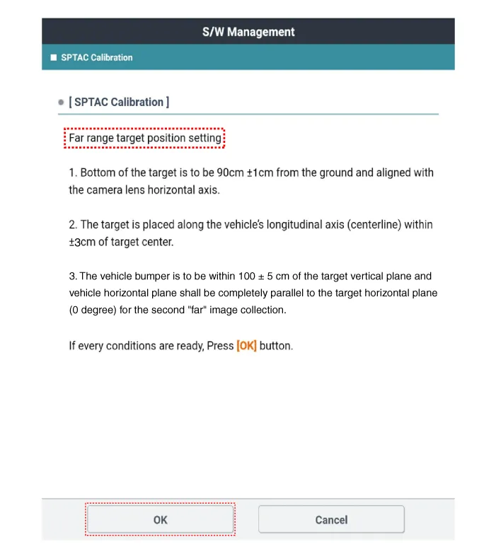
Set the calibration target height to 90 ± 1 cm (35.43 ± 0.39 in.) from the ground and align the center of calibration target with center line (A) of laser beam. The target is placed along the vehicle’s longitudinal axis (centerline) within ± 3cm (± 1.18 inch) of target center.
|
| 9. |
Perform the long-distance calibration by selecting the "OK" message on the KDS after checking the calibration target location.
|

| 10. |
Clear the diagnostic trouble codes (DTC) using the KDS. |
| 11. |
Check the DTC and warning lamp. |
Components and components location Components Location 1. Front view camera 2. AVN Head unit 3. Cluster 4. LFA,SCC ON/OFF switch (Remote control switch) 5.
Schematic diagrams Connector and Terminal Function Repair procedures Inspection 1. Disconnect the negative (-) battery terminal.
Other information:
Kia Optima DL3 2019-2026 Service and Repair Manual: Power Window Switch
Schematic diagrams Connector and Terminal Function Power Window Main Switch Pin Function 1 B-CAN (Low) 2 B-CAN (High) 3 Ground (Assist safety) 4 Assist safety 5
Kia Optima DL3 2019-2026 Service and Repair Manual: Evaporator Core
Repair procedures Replacement 1. Disconnect the negative (-) battery terminal. 2. Remove the heater and blower assembly. (Refer to Heater - "Heater Unit") 3. Loosen the mounting screws, lock pin and remove the evaporator core cover (A).
Categories
- Manuals Home
- Kia Optima Owners Manual
- Kia Optima Service Manual
- Engine Control / Fuel System
- Engine Control Module (ECM)
- Cooling System
- New on site
- Most important about car
