Kia Optima DL3: Lighting System / High Mounted Stop Lamp
Repair procedures
| Removal |
| 1. |
Disconnect the negative battery terminal. |
| 2. |
Remove the roof trim assembly. (Refer to Body - "Roof Trim Assembly") |
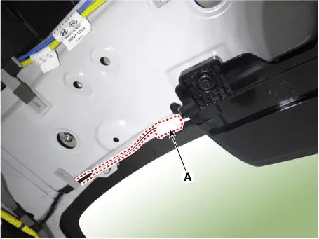
| 3. |
Disconnect the high mounted stop lamp connector (A).
|
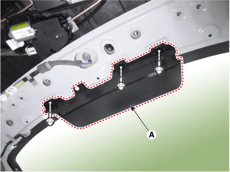
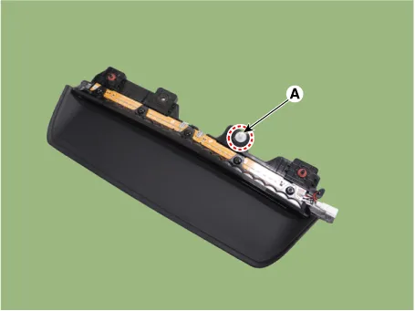
| 4. |
Remove the high mounted stop lamp (A) by loosening the mounting bolts.
|

| Installation |
| 1. |
Install in the reverse order of removal. |
Components and components location Component Location 1. Low beam 2. High beam 3. Daytime Running Light / Position lamp 4.
Repair procedures Removal 1. Disconnect the negative battery terminal. 2. Remove the lcense lamp (A) by pressing the hook.
Other information:
Kia Optima DL3 2019-2026 Service and Repair Manual: Smart Key System
Specifications Specifications Smart Key Unit Items Specification Rated voltage DC 12 V Operation voltage DC 9 - 16 V Operation temperature -40 to 185°F (-40 to 85°C) RF Receiver Items
Kia Optima DL3 2019-2026 Service and Repair Manual: Heater Core
Repair procedures Replacement 1. Disconnect the negative (-) battery terminal. 2. Remove the heater and blower assembly. (Refer to Heater - "Heater Unit") 3. Loosen the mounting screws and remove the heater core cover (A).
Categories
- Manuals Home
- Kia Optima Owners Manual
- Kia Optima Service Manual
- Automatic Transaxle System
- Brake System
- Battery
- New on site
- Most important about car
