Kia Optima DL3: Body Electrical System / Ignition Switch Assembly
Repair procedures
| Removal |
| 1. |
Disconnect the negative battery terminal. |
| 2. |
Remove the steering column upper & lower shroud panel. (Refer to Body - "Steering Column Shroud Panel") |
| 3. |
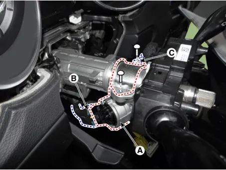
Remove the ignition lock switch assembly (A) by loosening the bolts after disconnecting the connectors (B, C).
|
| Installation |
| 1. |
Install in the reverse order of removal.
|

| Inspection |
| 1. |
Disconnect the ignition switch connector (B) and key warning switch connector (A) from under the steering column.
|
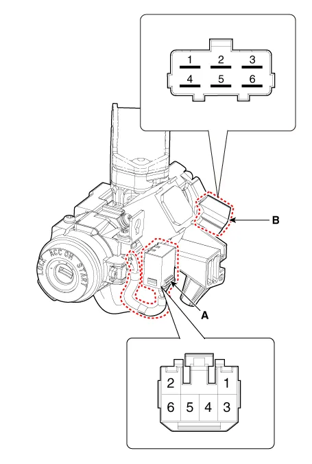
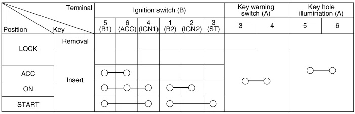
| 2. |
Check for continuity between the terminals.
|
Specifications Specifications Item Specification Remark Operating voltage 9 - 16 V - Current consumption MAX 5.
Other information:
Kia Optima DL3 2019-2026 Service and Repair Manual: Headlamps
Components and components location Component Location 1. Low beam 2. High beam 3. Daytime Running Light / Position lamp 4. Low assist beam 5. Turn signal lamp Schematic diagrams Connector and Terminal Function Connector Terminal Function
Kia Optima DL3 2019-2026 Service and Repair Manual: Power Seat Motor
Components and components location Components 1. Lumbar support motor 2. Reclining motor 3. Front height motor 4. Rear height motor 5. Slide motor Repair procedures Inspection 1.
Categories
- Manuals Home
- Kia Optima Owners Manual
- Kia Optima Service Manual
- Engine Mechanical System
- Heating, Ventilation and Air Conditioning
- Air bag collision sensors
- New on site
- Most important about car
