Kia Optima DL3: Driveshaft Assembly / Joint Assembly (Transaxle side)
Components and components location
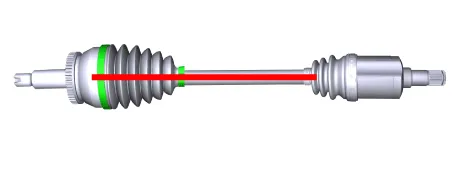
| Components |

| 1. Wheel side joint assembly
2. Wheel side circlip 3. Wheel side boot band 4. Wheel side boot |
5. Shaft 6. Transaxle side boot band 7. Transaxle side boot 8. Spider assembly |
9. Snap ring
10. Transaxle side joint case 11. Circlip |
Repair procedures
| Removal |
|

| 1. |
Remove the Front Driveshaft. (Refer to Driveshaft Assembly - “Front Driveshaft”) |
| 2. |
Remove both boot bands from the transaxle side joint.
|
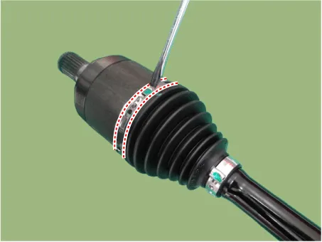
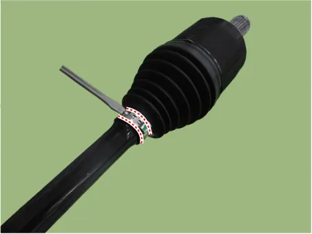
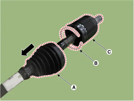
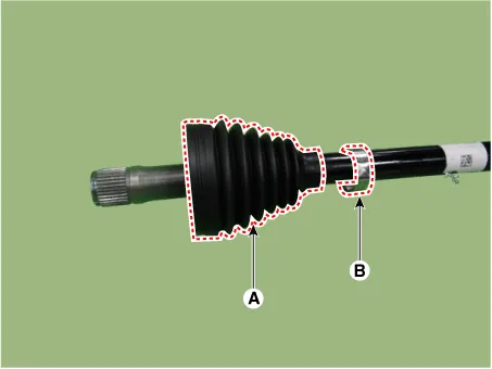
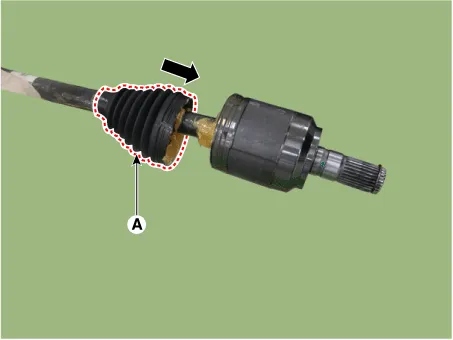
| 3. |
Remove the joint stopper ring (B) and the joint housing (C) after separating the transaxle side joint boot (A) in the direction of the arrow.
|
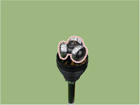
| 4. |
Remove the bearing from the spider assembly.
|
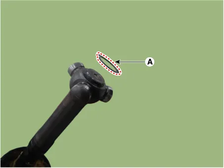
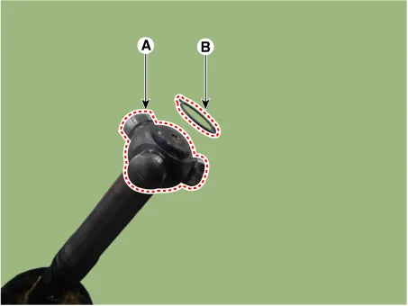
| 5. |
Use the snap ring pliers to remove the snap ring (A).
|
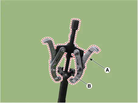
| 6. |
Remove spider assembly (B) from driveshaft using puller (A).
|
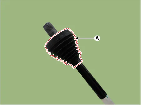
| 7. |
Remove the transaxle side joint boot (A).
|
| 8. |
Clean the spider assembly and joint housing. |
| Inspection |
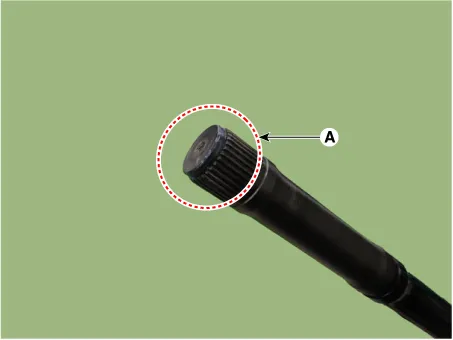
| 1. |
Check spline (A) for damage / wear / crack.
|
| 2. |
Check the boot for water or foreign objects. |
| 3. |
Check joint assembly for damage / wear / crack and rust. |
| 4. |
Replace any defective parts. |
| Installation |
|

| 1. |
Install the transaxle side boot (A) and boot band (B) on the driveshaft.
|
| 2. |
Install it in the order of spider assembly (A) and snap ring (B) in the driveshaft spline.
|
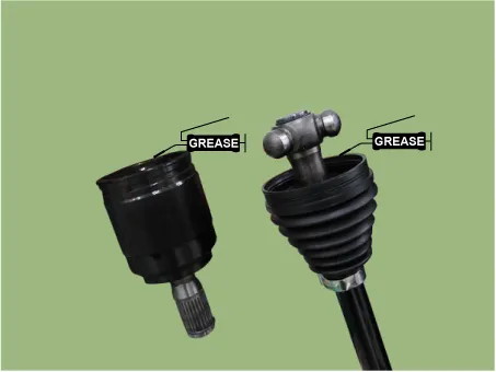
| 3. |
It applies a prescribed grease within the joint housing and the boot.
|
| 4. |
Install the bearing on the spider assembly.
|
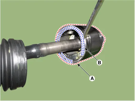
| 5. |
Assemble the transaxle side joint housing (A) to the driveshaft and mount the stopper ring (B).
|
| 6. |
Install the boot (A) on the joint housing.
|
| 7. |
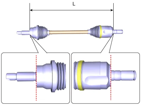
Set the distance between the driveshafts to the standard value and install the boot band to regulate the air in the transaxle boot.
|
|||||||||||
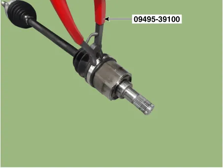
| 8. |
Install the large diameter boot band by using the SST (09495-39100).
|
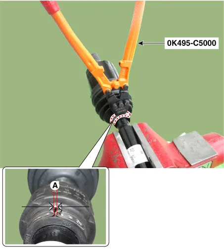
| 9. |
Install the small diameter boot band by using the SST (0K495-C5000).
|
| 10. |
Install the Front Driveshaft. (Refer to Driveshaft Assembly - “Front Driveshaft”) |
| 11. |
Check the front alignment. (Refer to Suspension System - "Front Alignment") |
Components and components location Components 1. Front driveshaft (LH) 2. Front driveshaft (RH) Repair procedures Removal 1.
Components and components location Components 1. Wheel side joint assembly 2. Wheel side circlip 3. Wheel side boot band 4.
Other information:
Kia Optima DL3 2019-2026 Service and Repair Manual: Vanity Lamp
Repair procedures Removal When removing with a flat-tip screwdriver or remover, wrap protective tape around the tools to prevent damage to components. 1.
Kia Optima DL3 2019-2026 Service and Repair Manual: Power Door Locks
C
Categories
- Manuals Home
- Kia Optima Owners Manual
- Kia Optima Service Manual
- Engine Control Module (ECM)
- Lift And Support Points
- Timing Chain
- New on site
- Most important about car
