Kia Optima DL3: Driveshaft Assembly / Joint Assembly (Wheel side)
Components and components location
| Components |
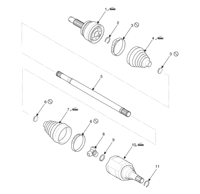
| 1. Wheel side joint assembly
2. Wheel side circlip 3. Wheel side boot band 4. Wheel side boott |
5. Shaft 6. Transaxle side boot band 7. Transaxle side boot 8. Spider assembly |
9. Snap ring
10. Transaxle side joint case 11. Circlip |
Repair procedures
| Removal |
| 1. |
Remove the Front Driveshaft. (Refer to Driveshaft Assembly - “Front Driveshaft”) |
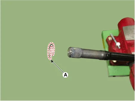
| 2. |
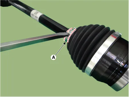
Use a screwdriver (-) to remove the small diameter boot band (A).
|
| 3. |
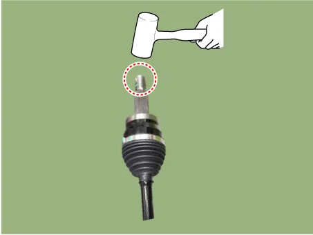
Using a plastic mallet, lower the top of the joint spline 2~3 times.
|

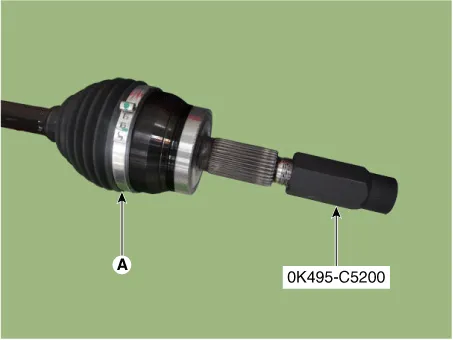
| 4. |
Tighten the SST (0K495-C5200) on the spline of the driveshaft (A).
|
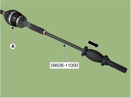
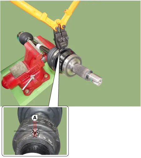
| 5. |
After fixing the driveshaft to the vise, remove the joint assembly (A) using a SST (09526-11000).
|
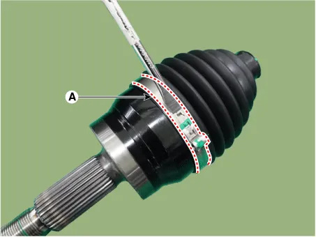
| 6. |
Use a screwdriver (-) to remover to remove the large diameter boot band (A).
|
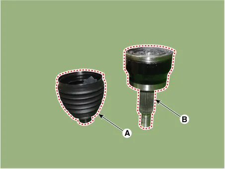
| 7. |
Remove the joint boot (A) and the joint assembly (B).
|
| 8. |
Remove the circlip (A) from the driveshaft.
|
| Inspection |
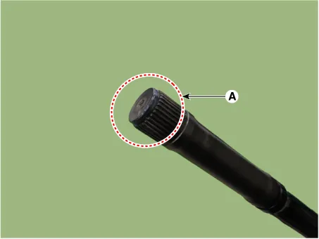
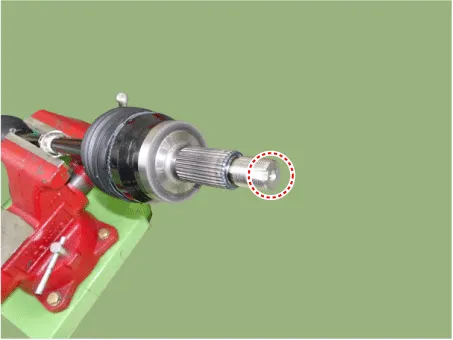
| 1. |
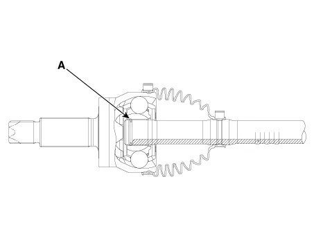
Check spline (A) for damage / wear / crack.
|
| 2. |
Check the boot for water or foreign objects. |
| 3. |
Check joint assembly for damage / wear / crack and rust. |
| 4. |
Replace any defective parts. |
| Installation |
|
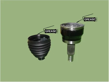
| 1. |
It applies a prescribed grease within the joint housing and the boot.
|
| 2. |
Install the wheel side boot band (A) and boot (B) to the driveshaft.
|

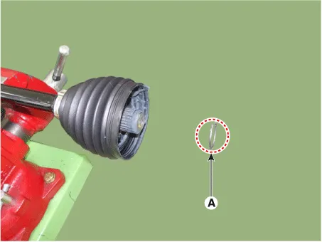
| 3. |
Fit the circlip (A) to the joint.
|
| 4. |
Insert the boot into the joint. |
| 5. |
Using a plastic mallet, lower the top of the joint spline 2~3 times.
|
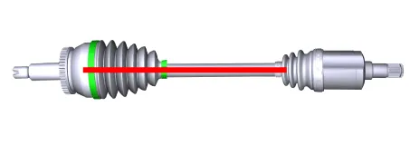
| 6. |
Set the distance between the driveshafts to the standard value and install the boot band to regulate the air in the wheel side boot.
|
|||||||||||

| 7. |
Install the small diameter boot band by using the SST (0K495-C5000).
|

| 8. |
Install the large diameter boot band by using the SST (0K495-C5000).
|
| 9. |
Install the Front Driveshaft. (Refer to Driveshaft Assembly - “Front Driveshaft”) |
| 10. |
Check the front alignment. (Refer to Suspension System - "Alignment") |
Components and components location Components 1. Wheel side joint assembly 2. Wheel side circlip 3. Wheel side boot band 4.
Service data Service Data Front Suspension Item Specification Suspension type Macpherson Strut Shock absorber type Gas Rear Suspension Item Specification Suspension type Multi link Shock absorber type Gas Wheel & Tire Item Specification Steel wheel 6.
Other information:
Kia Optima DL3 2019-2026 Service and Repair Manual: Overhead Console Lamp
Schematic diagrams Connector and Terminal Function [A Type] Connector A Pin E xcept Russia Region Russia only Function Function 1 Battery (+) Battery (+)
Kia Optima DL3 2019-2026 Service and Repair Manual: Power Door Mirror Switch
Schematic diagrams Connector and Terminal Function Pin Function 1 B-CAN (Low) 2 B-CAN (High) 3 Ground (Assist safety) 4 Assist safety 5 LIN (For IMS)
Categories
- Manuals Home
- Kia Optima Owners Manual
- Kia Optima Service Manual
- Battery
- Suspension System
- Identification Numbers
- New on site
- Most important about car
