Kia Optima DL3: Body Electrical System / Keyless Entry And Burglar Alarm
Specifications
| Specification |
|
Item |
Specification |
|
Operating temperature |
14 - 140°F (-10 - 60°C) |
|
RF Modulation |
FSK |
|
RF Frequency |
433.92 MHz |
|
LF Modulation |
ASK |
|
LF Frequency |
125 kHz |
|
Function |
Door lock |
|
Door unlock |
|
|
Trunk unlock |
|
|
Remote start |
Components and components location
| Component Location |
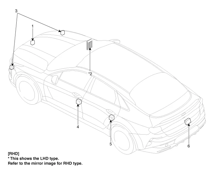
| 1. Hood switch 2. Integrated Body Control Unit (IBU) 3. Horn |
4. Front door actuator & switch
5. Rear door actuator & switch 6. Trunk actuator & switch |
Description and operation
| Description |
Burglar Alarm State [B/A State]
|
B/A State |
Description |
||||||||
|
DISARM |
|
||||||||
|
ARMWAIT |
|
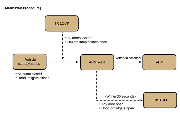
※ Remark: For a vehicle equipped with Smart Key system, the same process is applied to passive door lock function.
|
B/A State |
Description |
||||||||||||
|
AUTO LOCK TIMER 1 |
|

※ Remark: For a vehicle equipped with Smart Key system, the same process is applied to Passive door lock function.
|
B/A State |
Description |
||||||||||
|
AUTO LOCK TIMER 2 |
|
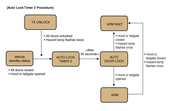
※ Remark: For a vehicle equipped with Smart Key system, the same process is applied to Passive door lock function.
|
B/A State |
Description |
|
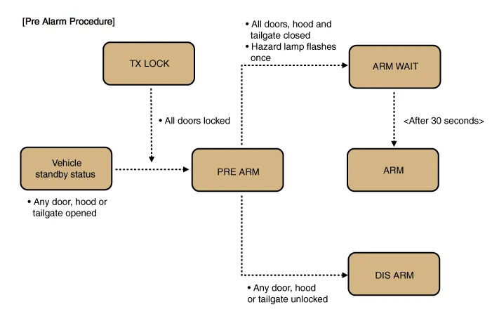
PRE ARM |
1-1. This is the state right before entering "ARM" mode after AUTO LOCK
Timer 2 is completed and all doors are closed. 1-2. If the driver closes hood or tailgate, hazard lamp blinks one time and then the vehicle automatically enters "ARM" mode via "ARM WAIT" mode. 2-1. If LOCK button is pressed while at least one of all doors, hood and tailgate is open, "PRE ARM" mode turns on. 2-2. Because all doors locking signal is issued but the conditions for "ARM WAIT" are not met, the vehicle remains in standby mode and enters ARM mode via ARM WAIT mode as soon as the door being open is closed. 2-3. In case intrusion is detected in PRE ARM mode, the vehicle turns into DISARM mode. 2-4. Security indicator keeps blinking in PRE ARM mode. |
|
B/A State |
Description |
||||||
|
RE ARM |
|
|
B/A State |
Description |
||||||||||
|
AUTOLOCK TIMER3 |
|
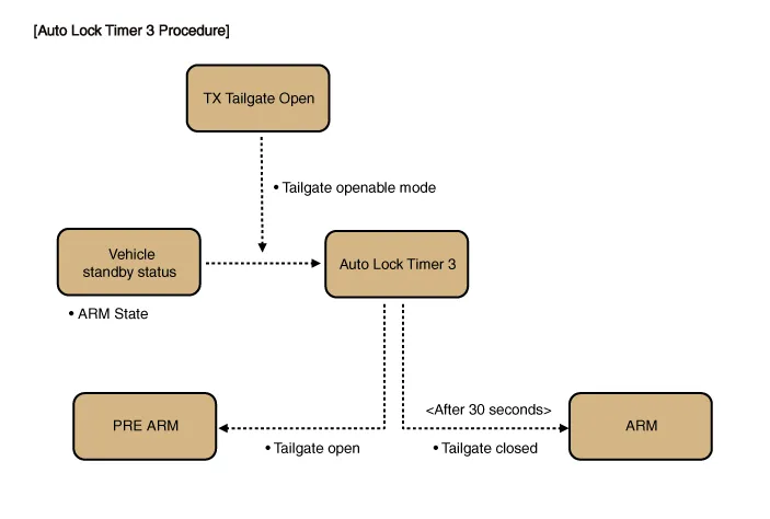
|
B/A State |
Description |
||||||||||||||
|
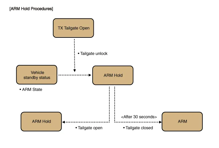
ARM HOLD (Alarm hold : Tailgate) ※Non-PTL option |
|
Note 1: ARM HOLD is a mode that defers activation of ARM mode only for tailgate. During ARM HOLD mode, ARM mode is applied to doors and hood.
Note 2: When using the ignition key to open the tailgate, the ARM HOLD function works in the same way, provided that the "Door Key Burglar Alarm" function should be enabled. if this is disabled, the key-based ARM HOLD is off and using the key to opening the tailgate is determined as a theft and the alarm is issued.
|
B/A State |
Description |
||||||
|
RE ARM (ARM mode is on again) |
|
||||||
|
RESET |
|
|
B/A State |
Description |
||||
|
KEY ON 30 second deactivation (Non-Smart Key option) |
|
||||
|
When ARM mode is on, the tailgate OPEN and central door unlock are not allowed.
|
|
Repair procedures
| Inspection |
When prying with a flat-tip screwdriver or use a prying trim tool, wrap it with protective tape, and apply protective tape around the related parts, to prevent damage. |

Front Door Lock Module
| 1. |
Disconnect the negative battery terminal. |
| 2. |
Remove the front door module. (Refer to Body - "Front Door Module") |
| 3. |
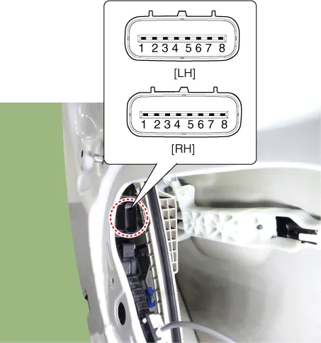
Disconnect the connector from the door lock actuator.
|
|||||||||||||||||||||||||||||
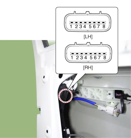
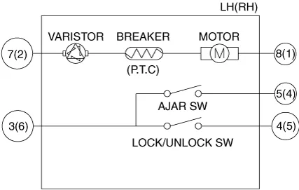
| 4. |
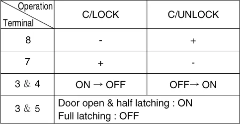
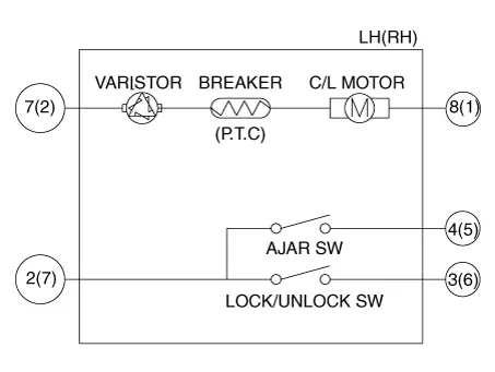
Check actuator operation by connecting power and ground as shown below. To prevent damage to the actuator, apply battery voltage only momentarily.
[LH]
[RH]
|
Rear Door Lock Module
| 1. |
Disconnect the negative battery terminal. |
| 2. |
Remove the rear door module. (Refer to Body - "Rear Door Module") |
| 3. |
Disconnect the connector from the door lock actuator.
|
|||||||||||||||||||||||||||||||||||||||||||||||||||||
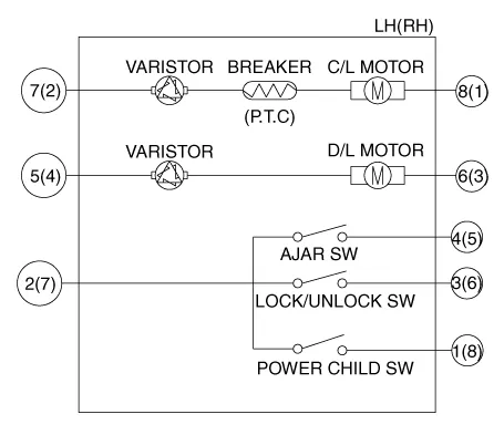
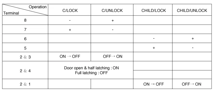
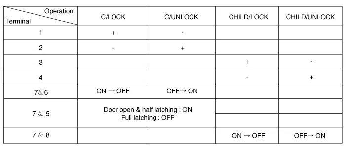
| 4. |
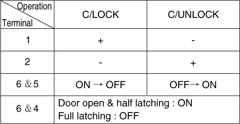
Check actuator operation by connecting power and ground as shown below. To prevent damage to the actuator, apply battery voltage only momentarily. [Central Lock]
[Power Child Lock]
[LH]
[RH]
|
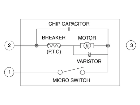
Trunk Lock Module
| 1. |
Disconnect the negative battery terminal. |
| 2. |
Remove the trunk lid trim. (Refer to Body - "Trunk Lid Trim") |
| 3. |
Disconnect the trunk lock module connector.
|
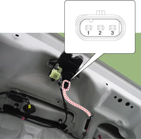
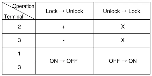
| 4. |
Check actuator operation by connecting power and ground as shown below. To prevent damage to the actuator, apply battery voltage only momentarily.
|
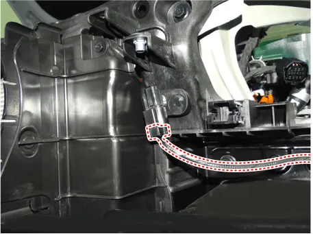
Hood Lock Module
| 1. |
Disconnect the negative battery terminal. |
| 2. |
Remove the left headlamp. (Refer to Lighting System - "Headlamps") |
| 3. |
Disconnect the hood switch connector.
|
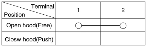
| 4. |
Check for continuity between the terminals.
|
| Removal |
Front Door Lock Module
| 1. |
Remove the front door latch. (Refer to Body - "Front Door Latch") |
Rear Door Lock Module
| 1. |
Remove the rear door latch. (Refer to Body - "Rear Door Latch") |
Trunk Lock Module
| 1. |
Remove the trunk lid latch. (Refer to Body - "Trunk Lid Latch") |
Hood Lock Module
| 1. |
Remove the hood latch. (Refer to Body - "Hood Latch") |
| Installation |
| 1. |
Install in the reverse of the removal. |
Components and components location Component Location 1. Integrated Body Control Unit (IBU) Schematic diagrams Connector and Terminal Function [Non-Smart key] Pin Function Connector A Connector B 1 - Front washer switch (Output) 2 Rear seat belt indicator_Left (Output) - 3 - Key solenoid (Output) 4 - Key in switch (Input) 5 - Key inter lock switch (Input) / 'P' : Position switch 6 Rear seat belt indicator_Center (Output) Wiper parking switch (Input) 7 - - 8 Rear seat belt indicator_Right (Output) Brake switch (Input) 9 - - 10 Headlamp high switch (Input) Front wiper volume switch (Input) 11 - Key hole illumination (Output) 12 - LIN4 (Safety ECU) 13 Rear view switch (Input) PAS Option (Input) 14 - - 15 RPAS Power (Output) B-CAN (Low) 16 FRAS Power (Output) B-CAN (High) 17 PAS/RPAS Power (Input) - 18 - Ground (Power) 19 - - 20 Ground (ECU) Immobilizer power (Output) 21 - Immobilizer ground (Output) 22 K-Line_Immobilizer Start inhibit relay 23 - PAS/RPAS Switch indicator (Output) 24 - Front wiper switch (Input) 25 Sunroof status (Input) - 26 PAS/RPAS Switch (Input) Multifunction switch ground (Input) 27 ATM Solenoid (Output) Wiper power relay (Output) 28 - Auto light sensor ground (Output) 29 LIN2 (ROA) Auto light sensor signal (Input) 30 LIN1 (PDW-F or PDW-R) Auto light sensor power (Output) 31 Door unlock signal (For IFU) EMS (Output) - 32 Light switch (Input) Front wiper high relay (Output) 33 Fog switch (Input) Front wiper low relay (Output) 34 IGN2 (Input) Front wiper low backup switch (Input) 35 IGN1 (Input) P-CAN (Low) 36 ACC (Input) P-CAN (High) 37 Battery + (ECU) 38 Battery + (Power) 39 - 40 Front heated nozzle (Output) [Smart key] Pin Function Connector A Connector B Connector C Connector D 1 - Front washer switch (Output) - Driver outside handle switch (Input) 2 Rear seat belt indicator_Left (Output) - ESCL Enable (Output) Assist outside handle switch (Input) 3 - - ESCL - (Output) - 4 - - - - 5 External buzzer (Output) - - RPM (Input) 6 Rear seat belt indicator_Center (Output) Wiper parking switch (Input) - SSB symbol illumination (+) (Output) 7 Puddle pocket lamp (Output) - ESCL Unlock switch (Input) ACC relay (Output) 8 Rear seat belt indicator_Right (Output) Brake switch (Input) - IGN1 relay (Output) 9 - - - IGN2 relay (Output) 10 Headlamp high switch (Input) Front wiper volume switch (Input) ESCL + (Output) Starter relay (Output) 11 - - Assist outside handle antenna (+) (Output) 12 - LIN4 (Safety ECU) Interior antenna 2 (+) (Output) 13 Rear view switch (Input) PAS Option (Input) Trunk interior antenna 3 (+) (Output) 14 - - Interior antenna 1 (+) (Output) 15 RPAS Power (Output) B-CAN (Low) Bumper antenna (+) (Output) 16 FRAS Power (Output) B-CAN (High) Driver outside handle antenna (+) (Output) 17 PAS/RPAS Power (Input) - - 18 - Ground (Power) - 19 - - - 20 Ground (ECU) Immobilizer power (Output) - 21 - Immobilizer ground (Output) SSB switch 1 (Input) 22 K-Line_Immobilizer - SSB switch 2 (Input) 23 - PAS/RPAS Switch indicator (Output) Clutch IGN lock switch 24 - Front wiper switch (Input) ESCL COM 25 Sunroof status (Input) - Wheel speed sensor (Input) 26 PAS/RPAS Switch (Input) Multifunction switch ground (Input) - 27 ATM Solenoid (Output) Wiper power relay (Output) - 28 LIN3 (Rain sensor) Auto light sensor ground (Output) - 29 LIN2 (ROA) Auto light sensor signal (Input) - 30 LIN1 (PDW-F or PDW-R) Auto light sensor power (Output) Start feed back (Input) 31 Door unlock signal (For IFU) EMS (Output) - Assist outside handle antenna (-) (Output) 32 Light switch (Input) Front wiper high relay (Output) Interior antenna 2 (-) (Output) 33 Fog switch (Input) Front wiper low relay (Output) Trunk interior antenna 3 (-) (Output) 34 IGN2 (Input) Front wiper low backup switch (Input) Interior antenna 1 (-) (Output) 35 IGN1 (Input) P-CAN (Low) Bumper antenna (-) (Output) 36 ACC (Input) P-CAN (High) Driver outside handle antenna (-) (Output) 37 Battery + (ECU) - 38 Battery + (Power) - 39 - - 40 Front heated nozzle (Output) 'P' Position (input) Description and operation Description Integrated Body Control Unit (IBU) Integrated body control unit has integrated several functions including body control module (IBU), smart key unit (SMK), and tire pressure monitoring system (TPMS).
Specifications Specification Item Tyep Watt (W) Front Headlamp A Type High beam LED - Low beam LED - Position/DRL LED - B Type High beam LED - Low beam LED - Low assist LED - Position/DRL LED - Turn signal lamp LED - Fog lamp LED - Turn signal lamp (Front air duct) PY21W 21 Turn signal lamp (Outside mirror side) LED - Rear Rear combination lamp A Type Tail/Stop lamp 21/5W 21/5 Tail lamp W5W 5 Turn signal lamp PY21W 21 Back up lamp W16W 16 B Type Tail/Stop lamp LED - Tail lamp LED - Turn signal lamp PY21W 21 Back up lamp W16W 16 High mounted stop lamp LED - License plate lamp W5W 5 Interior Overhead console lamp LED - Room lamp LED - Personal lamp LED - Vanity lamp W5W 5 Trunk room lamp FESTOON 5 Components and components location Component Location 1.
Other information:
Kia Optima DL3 2019-2026 Service and Repair Manual: Room Lamp
Repair procedures Removal When removing with a flat-tip screwdriver or remover, wrap protective tape around the tools to prevent damage to components. 1.
Kia Optima DL3 2019-2026 Service and Repair Manual: In-car Sensor
Description and operation Description The In-car air temperature sensor is built in the heater & A/C control unit. The sensor contains a thermistor which measures the temperature of the inside. The signal decided by the resistance value which changes in accordance with perceived inside temperature, is delivered to heater co
Categories
- Manuals Home
- Kia Optima Owners Manual
- Kia Optima Service Manual
- Motor Driven Power Steering
- Brake System
- Driving your vehicle
- New on site
- Most important about car
