Kia Optima DL3: Tires/Wheels / Alignment
Repair procedures
| Front Wheel Alignment |
|

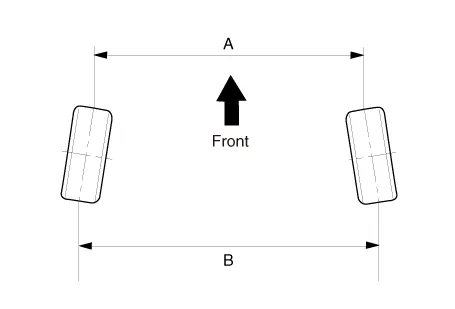
Toe
|
B - A > 0 : Toe in B - A < 0 : Toe out |
Toe Adjustment
| 1. |
Loosen the tie rod end lock nut. |
| 2. |
Remove the bellows clip to prevent the bellows from being twisted. |
| 3. |
Adjust the toe by screwing or unscrewing the tie rod. Toe adjustment should be made by turning the right and left tie rods by the same amount.
|
| 4. |
When completing the toe adjustment, install the bellows clip and tighten the tie rod end lock nut to specified torque.
|
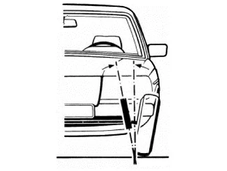
Camber
|
Camber : -0.5° ± 0.5° |
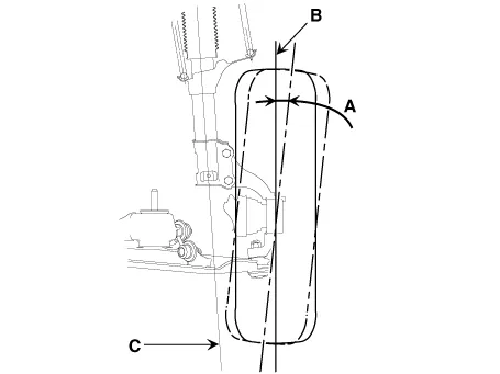
When the wheel tilts out at the top, then the camber is positive (+).
When the wheel tilts in at the top, then the camber is negative (-).
Camber and Caster are pre-set at the factory, so they do not need to be adjusted. If the camber and caster are not within the standard value, replace or repair the damaged parts and then inspect again.
|
ITEM |
Description |
|
A |
Positive camber angle |
|
B |
True vertical |
|
C |
Strut centerline |
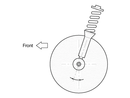
Caster
Caster is the tilting of the strut axis either forward or backward from vertical. A backward tilt is positive (+) and a forward tilt is negative (-).
Caster is pre-set at the factory and doesn't need to be adjusted. If the caster is not within the standard value, replace the bent or damaged parts.
|
Caster : 5.0° ± 0.5° |
King-pin angle
|
King-pin : 14.5° ± 0.5° |
|
| Rear Wheel Alignment |
|
Toe
|
B - A > 0: Toe in (+) B - A < 0: Toe out (-) |
Toe adjustment
| 1. |
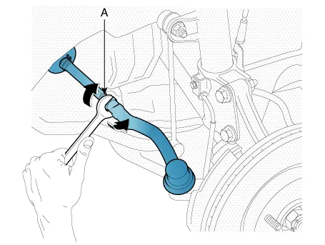
Loosen the nut holding the assist arm cam bolt (A). |
| 2. |
Adjust rear toe by turning the rear assist arm cam bolt (A) clockwise or counterclockwise. Toe adjustment should be made by turning the right and left cam bolt by the same amount.
|
| 3. |
When completing the toe adjustment, tighten the nut to specified torque.
|
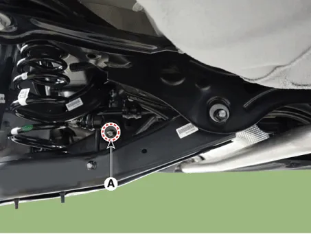
Camber
| 1. |
Loosen the nut holding the rear lower arm cam bolt (A). |
| 2. |
Adjust rear camber by turning the rear lower arm cam bolt (A) clockwise or counter clockwise. Rear camber adjustment should be made by turning the right and left cam bolt by the same amount.
|

| 3. |
When completing the toe adjustment, tighten the nut to specified torque.
|
Repair procedures Removal 1. Remove the wheel and tire (A). [Front] [Rear] Installation 1.
Components and components location Components 1. Integrated Body Control Unit (IBU) 2. TPMS sensor (FL) 3. TPMS sensor (RL) 4.
Other information:
Kia Optima DL3 2019-2026 Service and Repair Manual: Relaxion Comfort Seat
Components and components location Component Location 1. Relaxion comfort switch 2. Walk-in switch 3. Relaxion comfort seat unit (RCSU) Schematic diagrams Connector and Terminal Function Pin Function Connector A Co
Kia Optima DL3 2019-2026 Service and Repair Manual: Smart Key System
Specifications Specifications Smart Key Unit Items Specification Rated voltage DC 12 V Operation voltage DC 9 - 16 V Operation temperature -40 to 185°F (-40 to 85°C) RF Receiver Items
Categories
- Manuals Home
- Kia Optima Owners Manual
- Kia Optima Service Manual
- Front Axle Assembly
- Floor Console Assembly
- Cooling System
- New on site
- Most important about car
