Kia Optima DL3: Blower / Intake Actuator
Components and components location
| Components Location |
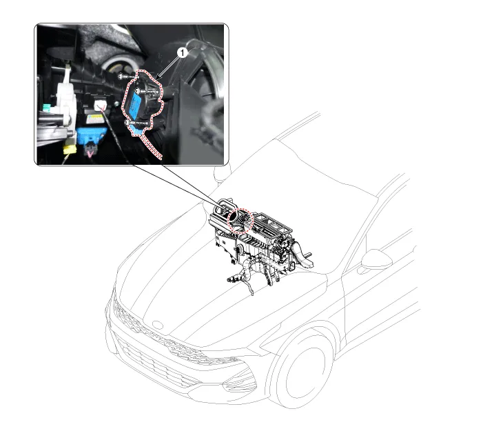
| 1. Intake actuator |
Description and operation
| Description |
The intake actuator is located at the blower unit. It regulates the intake door by a signal from the control unit. Pressing the intake selection switch will shift between recirculation and fresh air modes.
Repair procedures
| Inspection |
| 1. |
Turn the ignition switch OFF. |
| 2. |
Disconnect the intake actuator connector. |
| 3. |
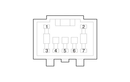
Verify that the intake actuator operates to the fresh position when connecting 12V to terminal 3 and grounding terminal 7. Verify that the intake actuator operates to the recirculation position when connected in reverse.
|
| 4. |
Connect the intake actuator connector. |
| 5. |
Turn the ignition switch ON. |
| 6. |
Check the voltage between terminal 6 and 5.
Specification
|

| 7. |
If the intake actuator does not operate well, substitute with a known-good intake actuator and check for proper operation. |
| 8. |
Replace the intake actuator if it is proved that there is a problem with it. |
| Replacement |
| 1. |
Disconnect the negative (-) battery terminal. |
| 2. |
Remove the main crash pad assembly. (Refer to Body - "Main Crash Pad Assembly") |
| 3. |
Separate the connector (A), loosen the mounting screws and remove the auto defogging actuator (B).
|
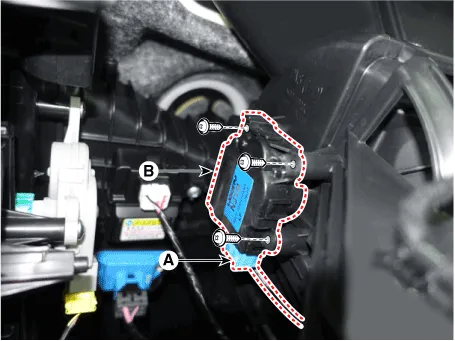
| 4. |
To install, reverse the removal procedure. |
Description and operation Description The climate control air filter is located in the blower unit. It eliminates foreign materials and odor.
Other information:
Kia Optima DL3 2019-2026 Service and Repair Manual: Lumbar Support System
Repair procedures Inspection 1. Remove the front seat back. (Refer to Body - "Front Seat Back Cover") 2. Disconnect the connector (A). 3. When the battery power is supplied to the motor connector, check the motor for smooth operation.
Kia Optima DL3 2019-2026 Service and Repair Manual: Washer Switch
R
Categories
- Manuals Home
- Kia Optima Owners Manual
- Kia Optima Service Manual
- Body (Interior and Exterior)
- Headlamps
- Floor Console Assembly
- New on site
- Most important about car
