
Kia Optima DL3: Roof Trim / Assist Handle
Components and components location
| Component Location |

| 1. Assist handle |
Repair procedures
| Replacement |
|

| 1. |
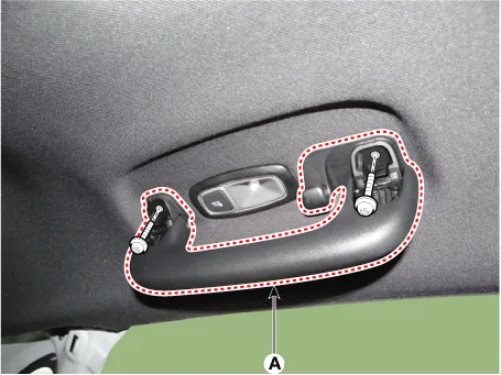
After lifting up the assist handle caps and loosening the mounting screws, remove the assist handle (A).
|
| 2. |
To install, reverse the removal procedure. |
Components and components location Component Location 1. Sunvisor 2. Retainer Repair procedures Replacement • When removing with a flat-tip screwdriver or remover, wrap protective tape around the tools to prevent damage to components.
Components and components location Component Location 1. Roof trim assembly Repair procedures Replacement • When removing with a flat-tip screwdriver or remover, wrap protective tape around the tools to prevent damage to components.
Other information:
Kia Optima DL3 2019-2026 Service and Repair Manual: Photo Sensor
Description and operation Description The photo sensor is located at the center of the defrost nozzles. The photo sensor contains a photovoltaic (sensitive to sunlight) diode. The solar radiation received by its light receiving portion, generates an electromotive force in proportion to the amount of radiation received which is
Kia Optima DL3 2019-2026 Service and Repair Manual: Auto Defoging Actuator
Components and components location Components Location 1. Auto logging actuator Description and operation Description The auto defogging sensor is installed on front window glass. The sensor judges and sends signal if moisture occurs to blow out wind for defogging.
Categories
- Manuals Home
- Kia Optima Owners Manual
- Kia Optima Service Manual
- Engine Control / Fuel System
- Heating, Ventilation and Air Conditioning
- Brake System
- New on site
- Most important about car
