Kia Optima DL3: Auto Lighting Control System / Auto Light Sensor
Schematic diagrams
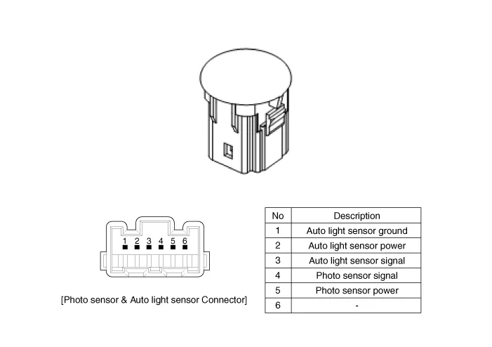
| Circuit Diagram |
Repair procedures
| Removal |
| 1. |
Disconnect the negative battery terminal. |
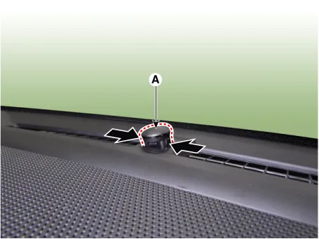
| 2. |
Remove the photo sensor & auto light sensor (A) by pressing the locking pins.
|
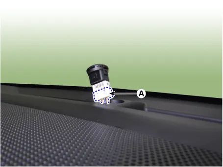
| 3. |
Disconnect the photo sensor & auto light sensor connector (A).
|
| Installation |
| 1. |
Install in the reverse order of removal. |
Specifications Specifications Items Specifications Rated voltage DC +5 V Load Max.
Components and components location Component Location 1. Audio head unit/AVN head unit 2. Tweeter speaker 3. Center speaker 4.
Other information:
Kia Optima DL3 2019-2026 Service and Repair Manual: Power Windows
Components and components location Component Location 1. Power window main switch 2. Rear window main switch 3. Front power window motor 4. Rear power window motor Description and operation Description Power Window Safety Function When the driver or passenger p
Kia Optima DL3 2019-2026 Service and Repair Manual: Walk-in Switch
Components and components location Component Location 1. Walk-in switch Repair procedures Removal When prying with a flat-tip screwdriver or use a prying trim tool, wrap it with protective tape, and apply prote
Categories
- Manuals Home
- Kia Optima Owners Manual
- Kia Optima Service Manual
- Engine Mechanical System
- Lift And Support Points
- Timing Chain
- New on site
- Most important about car
