Kia Optima DL3: Body Electrical System / Auto Lighting Control System
Specifications
| Specifications |
|
Items |
Specifications |
|
|
Rated voltage |
DC +5 V |
|
|
Load |
Max. 1 mA (Relay load) |
|
|
Illuminations (Lux) |
100 |
0.76 ± 0.17 V |
|
200 |
1.30 ± 0.30 V |
|
Components and components location
| Components |
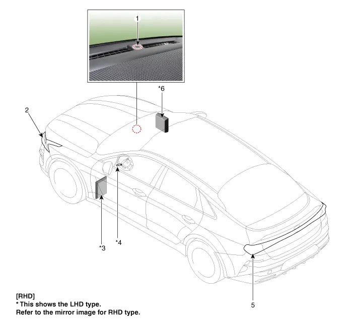
| 1. Auto light sensor 2. Head lamps 3. Integrated central control unit (ICU) |
4. Multifunction switch 5. Rear combination lamp 6. Integrated body control unit (IBU) |
Description and operation
| Description |
| • |
This system uses an illumination sensor to automatically turn ON the tail lamp and head lamp based on the ambient light change in surrounding environment's. |
| • |
It activates when the vehicle enters/exits tunnel, or when the illumination condition in surrounding environment changes due to rain, snow, or fog. |
General information General Troubleshooting Information Before Troubleshooting 1. Check applicable fuses in the appropriate fuse/relay box.
Schematic diagrams Circuit Diagram Repair procedures Removal 1. Disconnect the negative battery terminal.
Other information:
Kia Optima DL3 2019-2026 Service and Repair Manual: License Lamps
Repair procedures Removal 1. Disconnect the negative battery terminal. 2. Remove the lcense lamp (A) by pressing the hook. 3. Disconnect the lcense lamp connector (A).
Kia Optima DL3 2019-2026 Service and Repair Manual: Multifunction Switch
Specifications Specifications Items Specifications Rated voltage Front fog lamp switch 5 V Lighting Auto lighting Dimmer & Passing Turn signal lamp Wiper Was
Categories
- Manuals Home
- Kia Optima Owners Manual
- Kia Optima Service Manual
- Brake System
- Identification Numbers
- Body (Interior and Exterior)
- New on site
- Most important about car
