Kia Optima DL3: Interior Trim / Center Pillar Trim
Components and components location
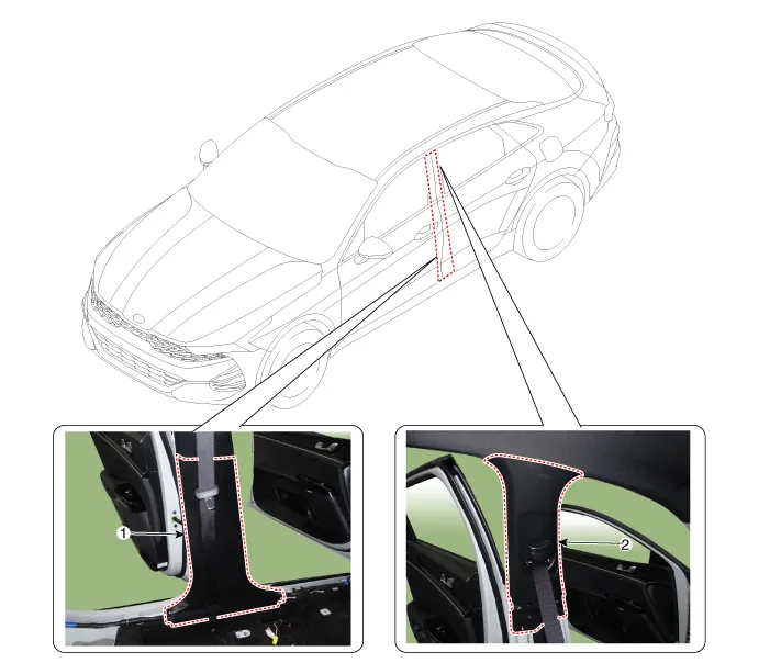
1. Center pillar lower trim
|
2. Center pillar upper trim
|
Repair procedures
[Center pillar lower
trim]
|
Put on gloves to prevent hand injuries.
|
| • |
When removing with a flat-tip screwdriver or remover, wrap protective
tape around the tools to prevent damage to components.
|
| • |
When removing the interior trim pieces, use a plastic panel removal
tool not to damage the surface.
|
| • |
Take care not to bend or scratch the trim and panels.
|
|
| 1. |
Remove the front door scuff trim.
(Refer to Interior Trim - "Door Scuff Trim")
|
| 2. |
Remove the rear door scuff trim.
(Refer to Interior Trim - "Door Scuff Trim")
|
| 3. |
Carefully remove the front door body side weatherstrip.
|
| 4. |
Carefully remove the rear door body side weatherstrip.
|
| 5. |
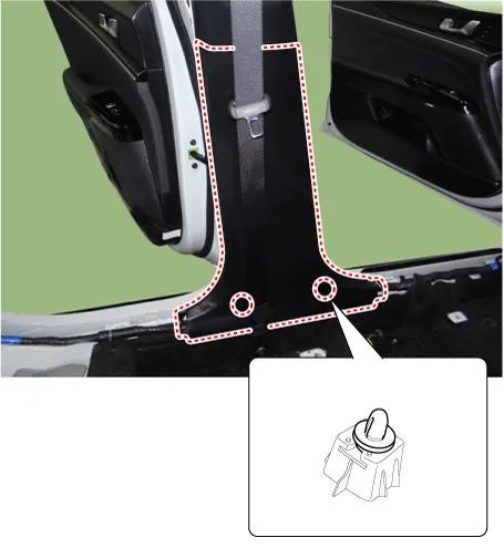
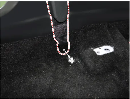
Using a screwdriver or remover, remove the center pillar lower trim (A).
|
| 6. |
To install, reverse the removal procedure.
|
Replace any damaged clips (or pin-type retainers).
|
|
[Center pillar upper
trim]
|
Put on gloves to prevent hand injuries.
|
| • |
When removing with a flat-tip screwdriver or remover, wrap protective
tape around the tools to prevent damage to components.
|
| • |
When removing the interior trim pieces, use a plastic panel removal
tool not to damage the surface.
|
| • |
Take care not to bend or scratch the trim and panels.
|
|
| 1. |
Remove the center pillar lower trim.
(Refer to Interior Trim - "Center Pillar Trim")
|
| 2. |
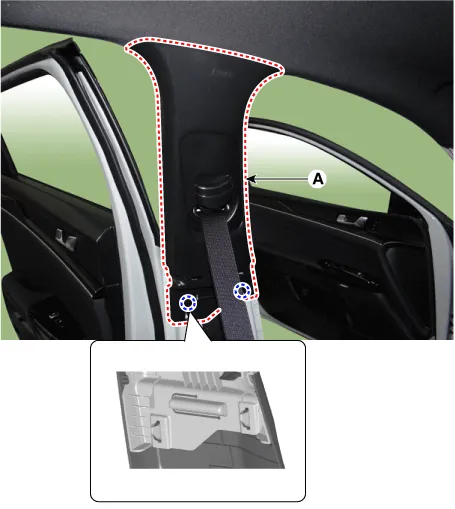
Open the front seat belt cover (A) and loosen the mounting bolt.
|
Tightening torque :
39.2 - 53.9 N.m (4.0 - 5.5 kgf.m, 28.8 - 39.8 lb-ft)
|
|
| 3. |
Using a screwdriver or remover, remove the center pillar upper trim (A).
|
| 4. |
To install, reverse the removal procedure.
|
Replace any damaged clips (or pin-type retainers).
|
|
Components and components location
Component Location
1. Front pillar trim
Repair procedures
Replacement
•
Put on gloves to prevent hand injuries.
Components and components location
Component Location
1. Rear pillar trim
Repair procedures
Replacement
•
When removing with a flat-tip screwdriver or remover, wrap protective
tape around the tools to prevent damage to components.
Other information:
Repair procedures
Inspection
When prying with a flat-tip screwdriver or use a prying trim tool, wrap
it with protective tape, and apply protective tape around the related parts,
to prevent damage.
Description and operation
Description
The ambient temperature sensor is located at the front of the condenser and detects
ambient air temperature. It is a negative type thermistor; resistance will increase
with lower temperature, and decrease with higher temperature.


