Kia Optima DL3: Crash Pad / Crash Pad Side Cover
Repair procedures
| Replacement |
|

| 1. |
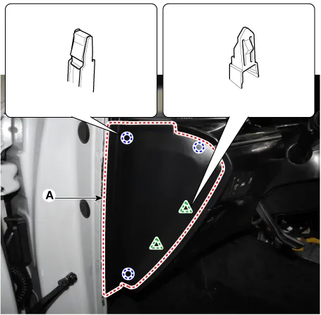
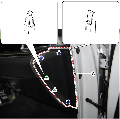
Using a remover and remove the crash pad side cover (A). [LH]
[RH]
|
| 2. |
To install, reverse the removal procedure.
|

Components and components location Component Location 1. Glove box Repair procedures Replacement • When removing with a flat-tip screwdriver or remover, wrap protective tape around the tools to prevent damage to components.
Repair procedures Replacement • When removing with a flat-tip screwdriver or remover, wrap protective tape around the tools to prevent damage to components.
Other information:
Kia Optima DL3 2019-2026 Service and Repair Manual: Wiper Motor
Schematic diagrams Connector and Terminal Function Pin Function 1 Ground (-) 2 Parking 3 Power (+) 4 Low 5 High Repair procedures Remova
Kia Optima DL3 2019-2026 Service and Repair Manual: In-car Sensor
Description and operation Description The In-car air temperature sensor is built in the heater & A/C control unit. The sensor contains a thermistor which measures the temperature of the inside. The signal decided by the resistance value which changes in accordance with perceived inside temperature, is delivered to heater co
Categories
- Manuals Home
- Kia Optima Owners Manual
- Kia Optima Service Manual
- Floor Console Assembly
- Body (Interior and Exterior)
- Engine Mechanical System
- New on site
- Most important about car
