Kia Optima DL3: Crash Pad / Glove Box
Components and components location
| Component Location |
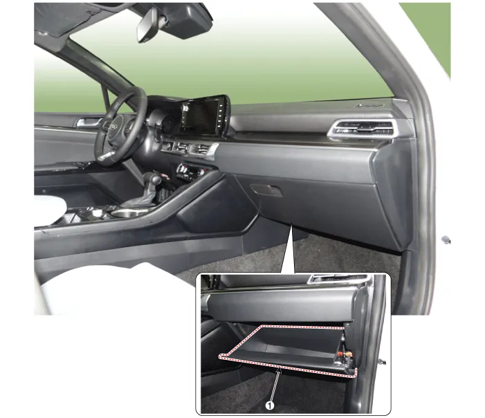
| 1. Glove box |
Repair procedures
| Replacement |
|

| 1. |
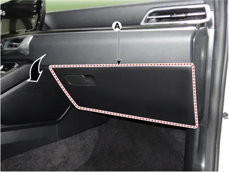
Open the glove box (A) in the direction of the arrow.
|
| 2. |
Separate the air damper (A) from the glove box.
|

| 3. |
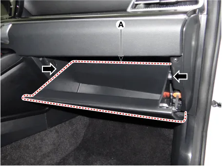
Press both sides inwards to open the glove box (A) downwards.
|
| 4. |
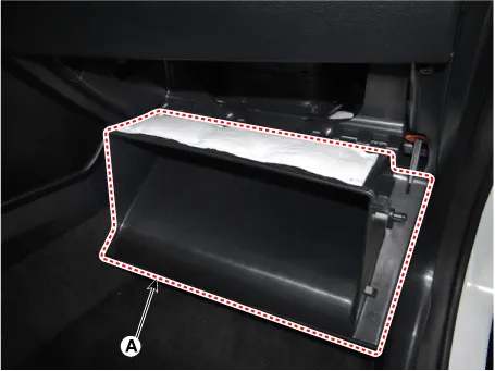
Remove the glove box (A).
|
| 5. |
To install, reverse removal procedure. |
Components and components location Component Location 1. Crash pad garnish [LH] 2. Crash pad garnish [RH] 3. Crash pad center garnish Repair procedures Replacement [Crash pad center garnish] • When removing with a flat-tip screwdriver or remover, wrap protective tape around the tools to prevent damage to components.
Repair procedures Replacement • When removing with a flat-tip screwdriver or remover, wrap protective tape around the tools to prevent damage to components.
Other information:
Kia Optima DL3 2019-2026 Service and Repair Manual: Integrated Memory Seat (IMS) Switch
Schematic diagrams Connector and Terminal Function Repair procedures Removal When prying with a flat-tip screwdriver or use a prying trim tool, wrap it with protective tape, and apply protective tape around the related parts, to prevent dam
Kia Optima DL3 2019-2026 Service and Repair Manual: Heated Seats Only
Components and components location Components Front Seat Heater 1. Front seat back heater 2. Front seat cushion heater 3. Front seat heater unit / ventilation unit Rear Seat Heater 1.
Categories
- Manuals Home
- Kia Optima Owners Manual
- Kia Optima Service Manual
- Brake System
- Engine Control / Fuel System
- Timing Chain
- New on site
- Most important about car
