Kia Optima DL3: Body (Interior and Exterior) / Fender
Components and components location
| Component Location |
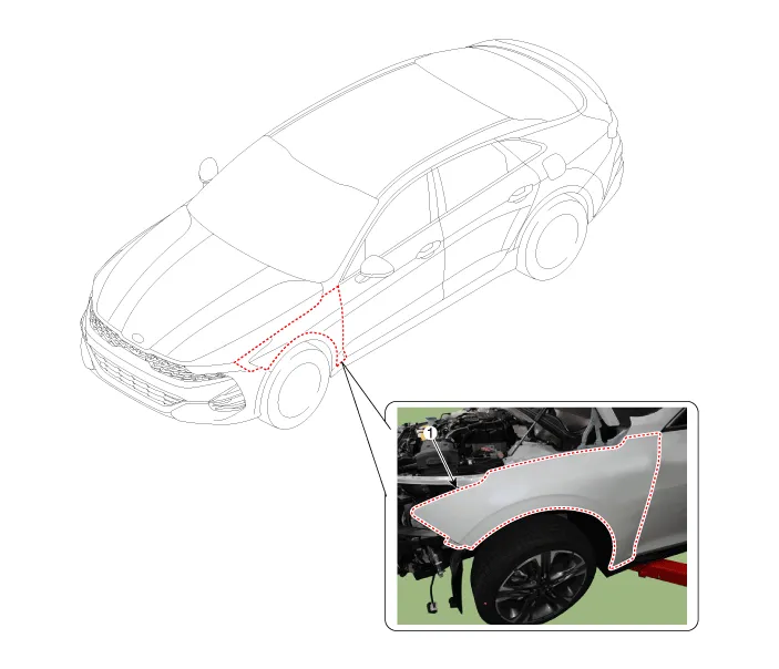
| 1. Fender assembly |
Repair procedures
| Replacement |
|

| 1. |
Remove the front bumper assembly. (Refer to Front Bumper - "Front Bumper Assembly") |
| 2. |
Remove the head lamps. (Refer to Body Electrical System - "Headlamps") |
| 3. |
Remove the side seal molding. (Refer to Body Side Molding - "Side Sill Molding") |
| 4. |
Remove the front wheel guard. (Refer to Body Side Molding - "Front Wheel Guard") |
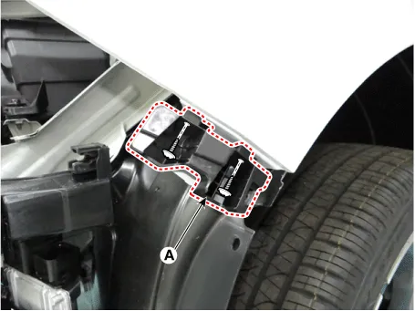
| 5. |
Loosen the mounting screws and remove the front bumper side mounting bracket (A).
|
| 6. |
Loosen the mounting bolts and remove the fender panel (A).
|
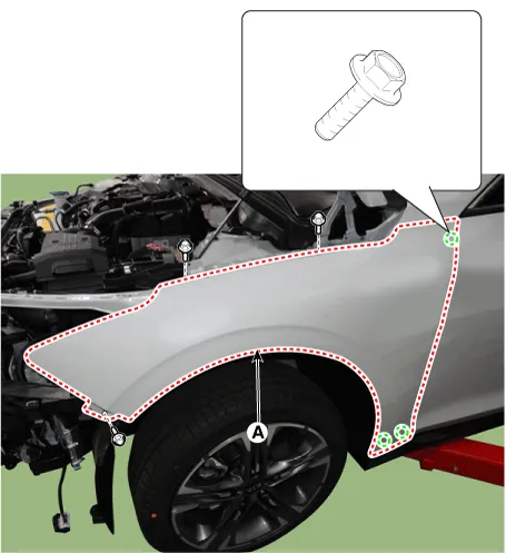
| 7. |
To install, reverse the removal procedure.
|

Service data Service Data Items Specification Hood Type Rear hinged, gas lifter type Front Door Construction Front hinged, frame door construction Regulator system Wire drum type Locking system Pin-fork system Rear Door Construction Front hinged, frame door construction Regulator system Wire drum type Locking system Pin-fork system Trunk Lid Type Front hinged Seat Belts Front 3 point type with Emergency Locking Retractor (E.
Repair procedures Adjustment 1. After loosening the hinge (A) mounting bolt, adjust the hood (B) by moving it up and down or from side to side and tighten the bolt.
Other information:
Kia Optima DL3 2019-2026 Service and Repair Manual: Power Windows
Components and components location Component Location 1. Power window main switch 2. Rear window main switch 3. Front power window motor 4. Rear power window motor Description and operation Description Power Window Safety Function When the driver or passenger p
Kia Optima DL3 2019-2026 Service and Repair Manual: In-car Sensor
Description and operation Description The In-car air temperature sensor is built in the heater & A/C control unit. The sensor contains a thermistor which measures the temperature of the inside. The signal decided by the resistance value which changes in accordance with perceived inside temperature, is delivered to heater co
Categories
- Manuals Home
- Kia Optima Owners Manual
- Kia Optima Service Manual
- Battery
- Charging System
- Engine Mechanical System
- New on site
- Most important about car
