Kia Optima DL3: Front Suspension System / Front Strut Assembly
Components and components location
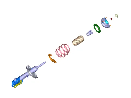
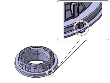
| Components |
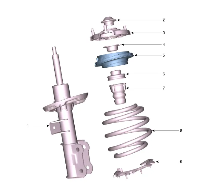
| 1. Strut assembly 2. Insulator dust cap 3. Insulator 4. Spring upper pad 5. Strut bearing |
6. Strut bearing pad 7. Bumper rubber 8. Coil spring 9. Spring lower pad |
Repair procedures
| Removal |
| 1. |
Disconnect the (-) battery terminal. |
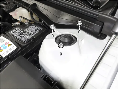
| 2. |
Loosen the front strut upper mounting nuts (A).
|
| 3. |
Remove the front wheel and tire. (Refer to Tires/Wheels - "Wheel") |
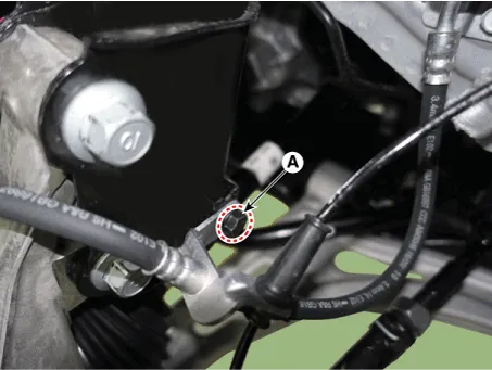
| 4. |
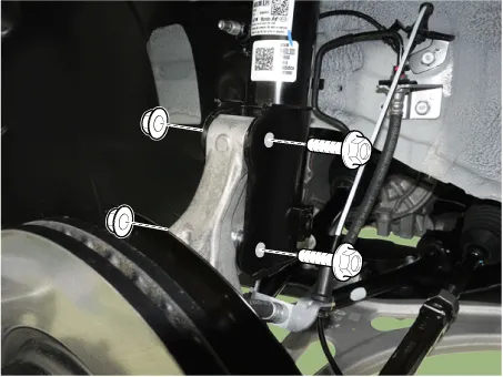
Loosen the mounting bolt (A) and then remove the brake hose bracket from the strut assembly.
|
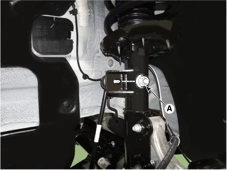
| 5. |
Disconnect the stabilizer link with the front strut assembly after loosening the nut (A).
|

| 6. |
Remove the front strut assembly from the front axle by loosening the bolts and nuts.
|
| Disassembly |
|

| 1. |
Remove the insulator dust cover (A).
|

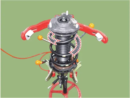
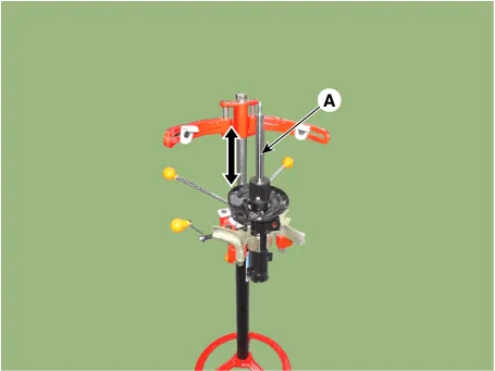
| 2. |
Using the spring compressor, compress the coil spring (A). Do not compress the spring more than necessary.
|
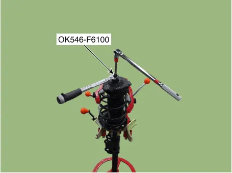
| 3. |
Using SST (0K546-F6100), loosen the self locking nut.
|
| 4. |
Remove the insulator, spring pad, coil spring and dust cover from the strut assembly.
|
| Inspection |
| 1. |
Check the strut bearing for wear and damage. |
| 2. |
Check the spring upper and lower seat for damage and deterioration. |
| 3. |
Compress and extend the piston rod (A) and check that there is no abnormal resistance or unusual sound during operation.
|
| Disposal |
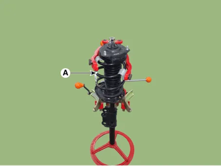
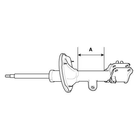
| 4. |
Fully extend the piston rod. |
| 5. |
Drill a hole on the A section to remove gas from the cylinder.
|

| Reassembly |
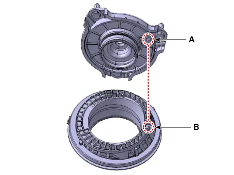
| 1. |
Install the insulator, spring pad, coil spring and dust cover from the strut assembly.
|
| 2. |
Compress and extend the piston rod (A) and check that there is no abnormal resistance or unusual sound during operation.
|
| 3. |
Using the special tool (0K546-F6100), install the self locking nut.
|
| 4. |
Install the insulator cap (A).
|
| Installation |
| 1. |
Install in the reverse order of removal. |
| 2. |
Check the alignment. (Refer to Suspension System - "Alingment") |
Components and components location Components 1. Strut complete 2. Roll rod bracket 3. Sub frame 4. Stabilizer bar 5.
Repair procedures Removal 1. Disconnect the (-) battery terminal. 2. Remove the front wheel and tire.
Other information:
Kia Optima DL3 2019-2026 Service and Repair Manual: Integrated Memory Seat (IMS) Unit
Specifications Specifications Item Specifications Rated voltage DC 12 V Operating voltage DC 9 - 16 V Operating temperature range -22 to 167°F (-30 to 75°C) Dark current Max.
Kia Optima DL3 2019-2026 Service and Repair Manual: Trunk Room Lamp
Repair procedures Removal 1. Disconnect the negative battery terminal. 2. Remove the trunk room lamp (A) by pressing the hook. 3. Disconnect the trunk room lamp connector (A).
Categories
- Manuals Home
- Kia Optima Owners Manual
- Kia Optima Service Manual
- Timing Chain
- Rear Brake Disc
- Charging System
- New on site
- Most important about car
