Kia Optima DL3: Fuel Delivery System / Fuel Tank
Specifications
| Specifications |
|
Item |
Specification |
|
|
Fuel Tank |
Capacity |
60 ℓ (15.8 U.S.gal., 63.4 U.S.qt., 52.8 lmp.qt.) |
Components and components location
| Component |
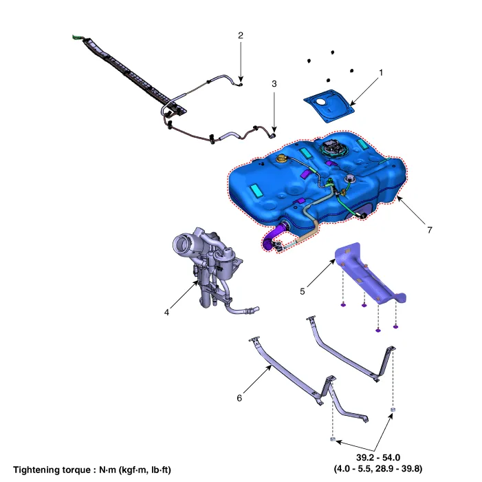
| 1. Service Cover 2. Fuel Feed Tube Quick-Connector 3. Vapor Tube quick-connector 4. Filler-neck assembly |
4. Heat Protector 5. Fuel Tank Band 5. Fuel Tank Complete |
Repair procedures
| Removal |
| 1. |
Release the residual pressure in the fuel line. (Refer to Fuel Delivery System - "Release Residual Pressure in Fuel Line") |
| 2. |
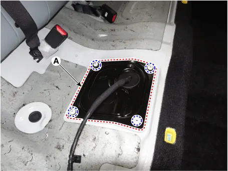
Remove the rear seat cushion. (Refer to Body - "Rear Seat Assembly") |
| 3. |
Remove the fuel pump service cover (A).
|
| 4. |
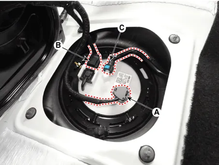
Disconnect the connectors (A, B, C). A : Fuel pump connector B : Fuel tank pressure sensor connector C : Fuel feed tube quick-connector
|
| 5. |
Remove the rear muffler. (Refer to Engine Mechanical System - "Muffler") |
| 6. |
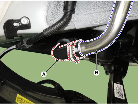
Separate the fuel filler hose (A) from the filler pipe (B) by releasing the clamp.
|
| 7. |
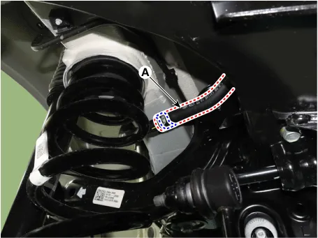
Separate the leveling hose-quick connector (A).
|

| 8. |
Separate the ventilation hose (A).
|
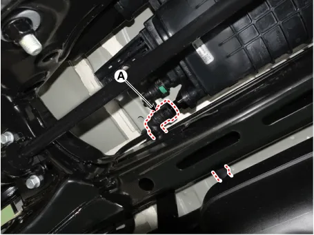
| 9. |
Separate vapor hose hose quick-connector (A).
|
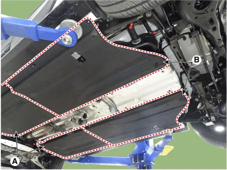
| 10. |
Remove the front floor under cover (A) and the rear floor under cover (B).
|
| 11. |
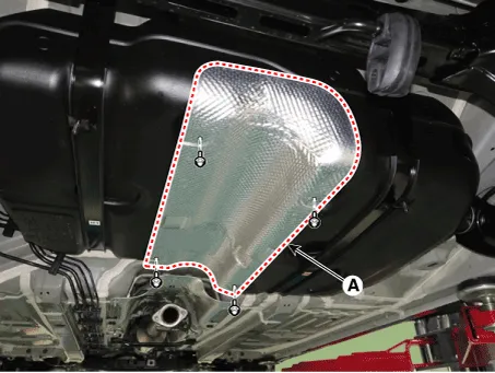
Remove the heat protector (A).
|
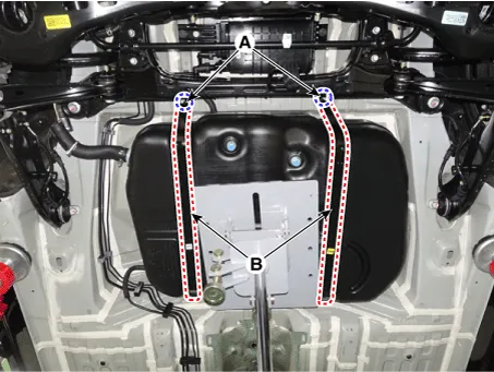
| 12. |
Support the fuel tank with a jack. |
| 13. |
Remove the fuel tank band (B) after loosening the mounting nuts (A).
|
| 14. |
Remove the fuel tank from the vehicle. |
| Installation |
| 1. |
Install in the reverse order of removal. |
Fuel pressure test Fuel Pressure Test 1. Release the residual pressure in fuel line. (Refer to Fuel Delivery System - "Release Residual Pressure in Fuel Line") When removing the fuel pump relay, a Diagnostic Trouble Code (DTC) may occur.
Specifications Specification Items Specification Current (A) Max. 6.0 Supply Voltage (V) 12 Fuel Pressure bar 3.
Other information:
Kia Optima DL3 2019-2026 Service and Repair Manual: Power Windows
Components and components location Component Location 1. Power window main switch 2. Rear window main switch 3. Front power window motor 4. Rear power window motor Description and operation Description Power Window Safety Function When the driver or passenger p
Kia Optima DL3 2019-2026 Service and Repair Manual: Wiper Arm
Repair procedures Removal 1. If necessary, remove the blade by pushing it in the direction arrow after opening the hook (A). • Move the windshield glass wiper blades to the servic
Categories
- Manuals Home
- Kia Optima Owners Manual
- Kia Optima Service Manual
- Battery
- Motor Driven Power Steering
- Automatic Transaxle System
- New on site
- Most important about car
