Kia Optima DL3: Engine Control / Fuel System / Fuel Delivery System
Fuel pressure test
| Fuel Pressure Test |
| 1. |
Release the residual pressure in fuel line. (Refer to Fuel Delivery System - "Release Residual Pressure in Fuel Line")
|

| 2. |
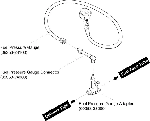
Install the Special Service Tool (SST).
|
| 3. |
Inspect fuel leakage on connections among the fuel feed tube, the delivery pipe, and the SST components with IG ON. |
| 4. |
Measure Fuel Pressure.
|

| 5. |
Release the residual pressure in fuel line. (Refer to Fuel Delivery System - "Release Residual Pressure in Fuel Line")
|
| 6. |
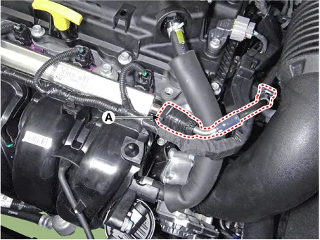
Remove the SSTs from the fuel feed tube and the delivery pipe. |
| 7. |
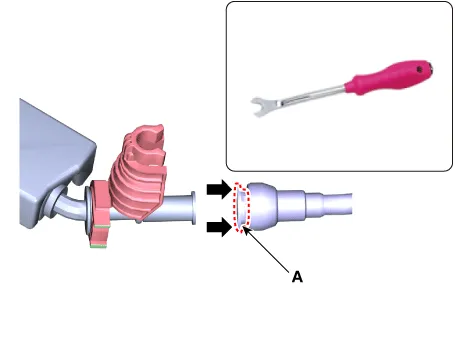
Install the fuel feed tube from the delivery pipe. |
Release residual pressure in fuel line
| Release Residual Pressure in Fuel Line |
There may be some residual pressure even after “Release Residual Pressure in Fuel Line” work, so cover the hose connection with a shop towel to prevent residual fuel from spilling out before disconnecting any fuel connection. |
| 1. |
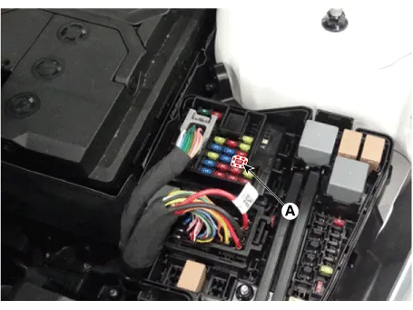
After disconnecting the negative battery terminal, remove the fuel pump fuse (A).
|
| 2. |
Connect the negative battery terminal. |
| 3. |
After starting the engine and let idle, turn the ignition switch OFF after the engine has stopped on its own. |
| 4. |
Install the fuel pump after disconnecting the battery negative (-) terminal, install the fuel pump fuse. |
| 5. |
Delete the Diagnostic Trouble Code (DTC) related the fuel pump fuse with the KDS. |
- Fuel Tank
- Fuel Pump Module
- Fuel Filter
- Fuel Pump & Tube Assembly
- Fuel Sender
- Fuel Pressure Regulator
- Fuel Line
- Filler-Neck Assembly
- Delivery Pipe
- Injector
Description and operation Description • The Variable Charge Motion Actuator (VCMA) is installed on the inlet of the intake manifold.
Specifications Specifications Item Specification Fuel Tank Capacity 60 ℓ (15.
Other information:
Kia Optima DL3 2019-2026 Service and Repair Manual: Personal Lamp
Repair procedures Removal When removing with a flat-tip screwdriver or remover, wrap protective tape around the tools to prevent damage to components. 1.
Kia Optima DL3 2019-2026 Service and Repair Manual: Heating, Ventilation and Air Conditioning
Service data Service Data Air Conditioner ltem Specification Compressor Type 6SAS14 Oil type & Capacity ND-OIL 12 80 ± 10 cc (2.82 ± 0.
Categories
- Manuals Home
- Kia Optima Owners Manual
- Kia Optima Service Manual
- Body Electrical System
- Timing Chain
- Brake System
- New on site
- Most important about car
