
Kia Optima DL3: Body Electrical System / Headlamp Leveling System
Schematic diagrams
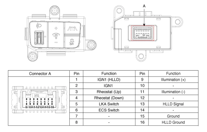
| Connector and Terminal Function |
Repair procedures
| Removal |
| 1. |
Disconnect the negative battery terminal. |
| 2. |
Remove the crash pad lower panel. (Refer to Body - "Crash Pad Lower Panel") |
| 3. |
Remove the crash pad garnish [LH]. (Refer to Body - "Crash Pad Garnish") |
| 4. |
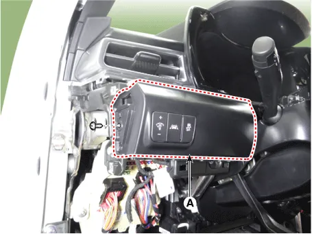
Remove the crash pad lower garnish [LH] (A) by loosening the mounting screw.
|
| 5. |
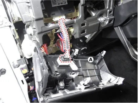
Disconnect the connector (A) from the crash pad lower garnish [LH].
|
| 6. |
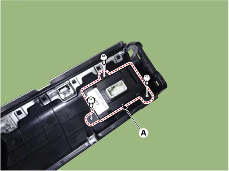
Remove the side crash pad switch (A) by loosening the mounting screws.
|
| Installation |
| 1. |
Install in the reverse of the removal. |
Repair procedures Removal 1. Disconnect the negative battery terminal. 2. Remvoe the fuel door housing.
Components and components location Components Location 1. Rain sensor 2. Head up display (HUD) unit 3. Instrument cluster Description and operation Description HUD system displays various information on the windshield glass which minimizes the driver’s eye movement to enhance safety and convenience.
Other information:
Kia Optima DL3 2019-2026 Service and Repair Manual: Hazard Lamp Switch
Schematic diagrams Connector and Terminal Function Repair procedures Removal 1. Disconnect the negative battery terminal. 2. Remove the crash pad garnish [RH]. (Refer to Body - "Crash Pad Garnish") 3.
Kia Optima DL3 2019-2026 Service and Repair Manual: Heater Control Unit
Components and components location Components Connector Pin Function [Connector A] Pin NO Funtion Pin NO Funtion 1 Ground 11 Ground 2 Clean signal 12 -
Categories
- Manuals Home
- Kia Optima Owners Manual
- Kia Optima Service Manual
- Motor Driven Power Steering
- Air bag collision sensors
- Engine Mechanical System
- New on site
- Most important about car
