Kia Optima DL3: Brake System / Rear Brake Caliper
Components and components location
| Components |
| [EPB Apply] |
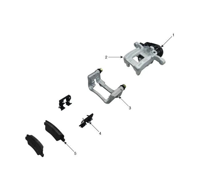
| 1. EPB Actuator 2. Caliper body 3. Caliper carrier |
4. Pad retainer 5. Brake pad |
| [EPB None Apply] |
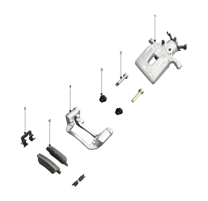
| 1. Caliper body 2. Guide rod pin 3. Guide rod boot |
4. Caliper carrier 5. Pad retainer 6. Brake pad |
Repair procedures
| Removal |
[EPB Apply]
| 1. |
Release the parking brake. |
| 2. |
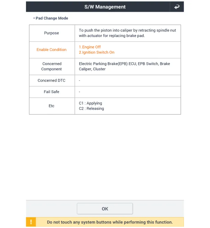
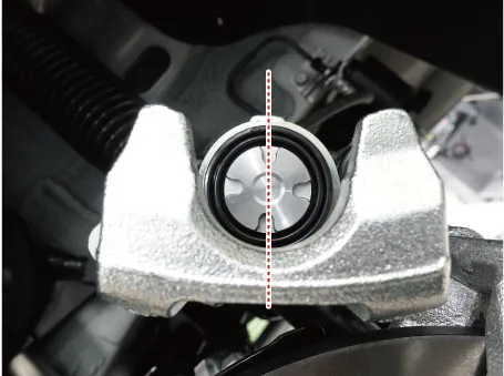
Before removing the rear caliper, perform “Brake Pad Replacement Mode” using the KDS.
|

| 3. |
Select C2 (Release) on the screen below.
|

| 4. |
Disconnect the (-) battery terminal. |
| 5. |
Remove the rear wheel and tire. (Refer to Suspension System - "Wheel") |
| 6. |
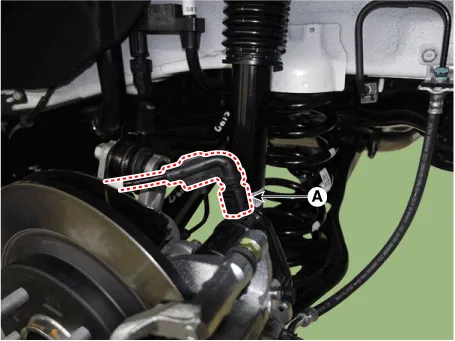
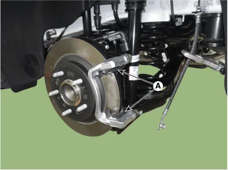
Disconnect the EPB actuator connector (A).
|
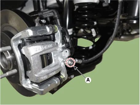
| 7. |
Remove the hose after loosening the brake hose bolt (A) from the caliper.
|

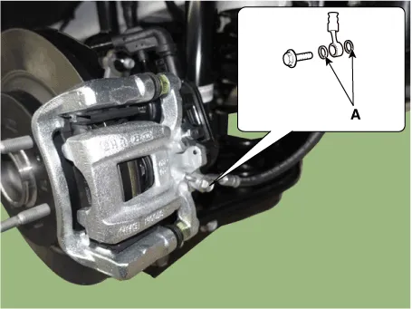
| 8. |
Remove the caliper body (A) after loosening the guide rod bolt.
|
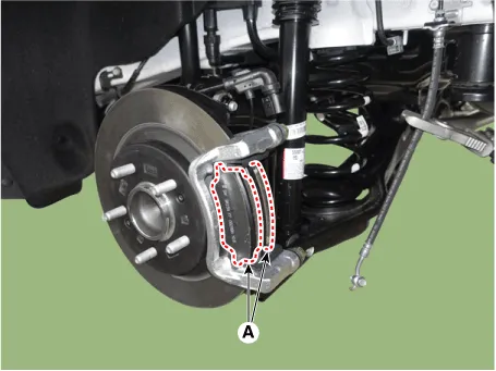
| 9. |
Remove the brake pad (A).
|
| 10. |
Remove the pad retainer (A).
|
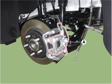
| 11. |
Remove the caliper carrier (A) after loosening the caliper mounting bolt.
|
[EPB None Apply]
| 1. |
Release the parking brake. |
| 2. |
Disconnect the (-) battery terminal. |
| 3. |
Remove the rear wheel and tire. (Refer to Suspension System - "Wheel") |
| 4. |
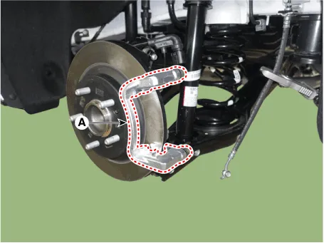
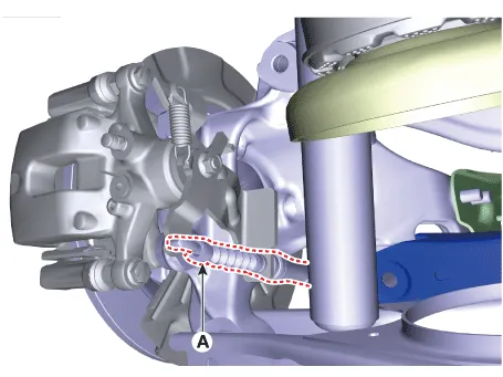
Disconnect the parking cable (A) after remove the parking brake cable fixing clip.
|
| 5. |
Loosen the brake hose bolt (A) from the caliper seperate the brake hose.
|
| 6. |
Remove the caliper body (A) after loosening the guide rod bolt.
|
| 7. |
Remove the brake pad (A).
|
| 8. |
Remove the pad retainer (A).
|
| 9. |
Remove the caliper carrier (A) after loosening the caliper mounting bolt.
|
| Installation |
| 1. |
Install in the reverse order of removal. |
| 2. |
Use a SST (09580-0U000) when installing the brake caliper assembly.
|
| 3. |
After installation, bleed the brake system. (Refer to Brake system - "Brake Bleeding Procedures") |
| 4. |
Apply the parking brake several times and check for normal operation.
|
| 5. |
Check the spilled brake oil. |
| 6. |
Apply the parking brake several times and check for normal operation. |
Components and components location Components 1. Front Brake Caliper 2. Front Brake Disc 3. Front Axle Repair procedures Removal 1.
Components and components location Components 1. Rear brake disc 2. Hub bearing assembly 3. Dust cover 4.
Other information:
Kia Optima DL3 2019-2026 Service and Repair Manual: Smart Key Antenna
Repair procedures Removal Interior Antenna 1 1. Disconnect the negative battery terminal. 2. Remove the surround view monitor (SVM) unit. (Refer to Advanced Driver Assistance System (ADAS) - "Surround View Monitor (SVM) Unit") 3.
Kia Optima DL3 2019-2026 Service and Repair Manual: Heater & A/C Control Unit (DATC)
Components and components location Components Connector Pin NO Funtion Pin NO Funtion 1 Ground 9 Ground 2 ILL- 10 - 3 - 11
Categories
- Manuals Home
- Kia Optima Owners Manual
- Kia Optima Service Manual
- Battery
- Heating, Ventilation and Air Conditioning
- Motor Driven Power Steering
- New on site
- Most important about car
