Kia Optima DL3: Brake System / Front Brake Disc
Components and components location
| Components |

| 1. Front Brake Caliper 2. Front Brake Disc |
3. Front Axle |
Repair procedures
| Removal |
| 1. |
Disconnect the (-) battery terminal. |
| 2. |
Remove the front wheel and tire. (Refer to Suspension System - "Wheel") |
| 3. |
Loosen the guide rod bolt and then pivot the caliper body (A) up out of the way.
|

| 4. |
Remove the brake pad (A).
|

| 5. |
Remove the pad retainer (A).
|
| 6. |
Remove the caliper carrier (A) by loosening the caliper mouniting bolts.
|


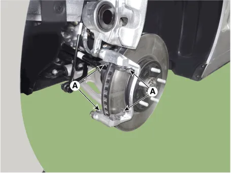
| 7. |
Remove the front brake disc (A) by loosening the screws.
|

| Inspection |
Front Brake Disc Thickness Check
| 1. |
Check the brake disc for damage and cracks. |
| 2. |
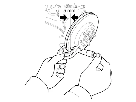
Remove all rust and contamination from the surface, and measure the disc thickness at 8 points, at least, of same distance (5mm) from the brake disc outer circle.
|
| 3. |
If wear exceeds the limit, replace the discs and pad assembly left and right of the vehicle. |
Front Brake Disc Runout Check
| 1. |
Place a dial gauge about 5mm (0.20 in) from the outer circumference of the brake disc, and measure the runout of the disc.
|

| 2. |
If the runout of the brake disc exceeds the limit specification, replace the disc, and then measure the runout again. |
| 3. |
If the runout does not exceed the limit specification, install the brake disc after turning it 180° and then check the runout of the brake disc again. |
| Installation |
| 1. |
Install in the reverse order of removal. |
| 2. |
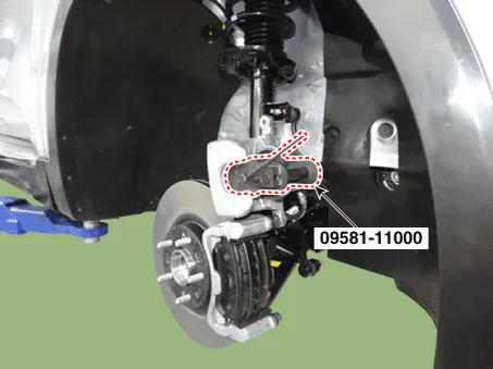
Use a SST (09581-11000) when installing the brake caliper assembly.
|
| 3. |
After installation, bleed the brake system. (Refer to Brake System - "Brake Bleeding Prcoedures") |
| 4. |
Check the brake oil leakage and pedal operating condition. |
Components and components location Components 1. Caliper body 2. Caliper carrier 3. Pad inner shim 4. Brake pad 5.
Components and components location Components [EPB Apply] 1. EPB Actuator 2. Caliper body 3. Caliper carrier 4.
Other information:
Kia Optima DL3 2019-2026 Service and Repair Manual: Fog Lamp
Repair procedures Removal Front Fog Lamp 1. Disconnect the negative battery terminal. 2. Remove the front bumper assembly. (Refer to Body - "Front Bumper Assembly") 3.
Kia Optima DL3 2019-2026 Service and Repair Manual: Trunk Room Lamp
Repair procedures Removal 1. Disconnect the negative battery terminal. 2. Remove the trunk room lamp (A) by pressing the hook. 3. Disconnect the trunk room lamp connector (A).
Categories
- Manuals Home
- Kia Optima Owners Manual
- Kia Optima Service Manual
- Engine Mechanical System
- Lift And Support Points
- Headlamps
- New on site
- Most important about car
