Kia Optima DL3: Smart Key System / Smart Key Diagnostic
Repair procedures
| Inspection |
| 1. |
In the body electrical system, failure can be quickly diagnosed by using the vehicle diagnostic system (KDS). The diagnostic system (KDS) provides the following information.
|
| 2. |
Select the "Car model" and the 'IBU-SMK' to be checked in order to check the vehicle with the tester. |
| 3. |
Select the 'Current Data' menu to search the current state of the input/output data. |
| 4. |
If you want to check each module operation forcefully, select "Actuation test". |
Antenna Actuation Diagnosis
| 1. |
Connect the cable of KDS to the data link connector in driver side crash pad lower panel. |
| 2. |
After IG ON, select the "Actuation Test". |
| 3. |
Set the smart key near the related antenna and operate it with a KDS. |
| 4. |
If the LED of smart key is blinking, the smart key is normal. |
| 5. |
If the LED of smart key is not blinking, check the voltage of smart key battery. |
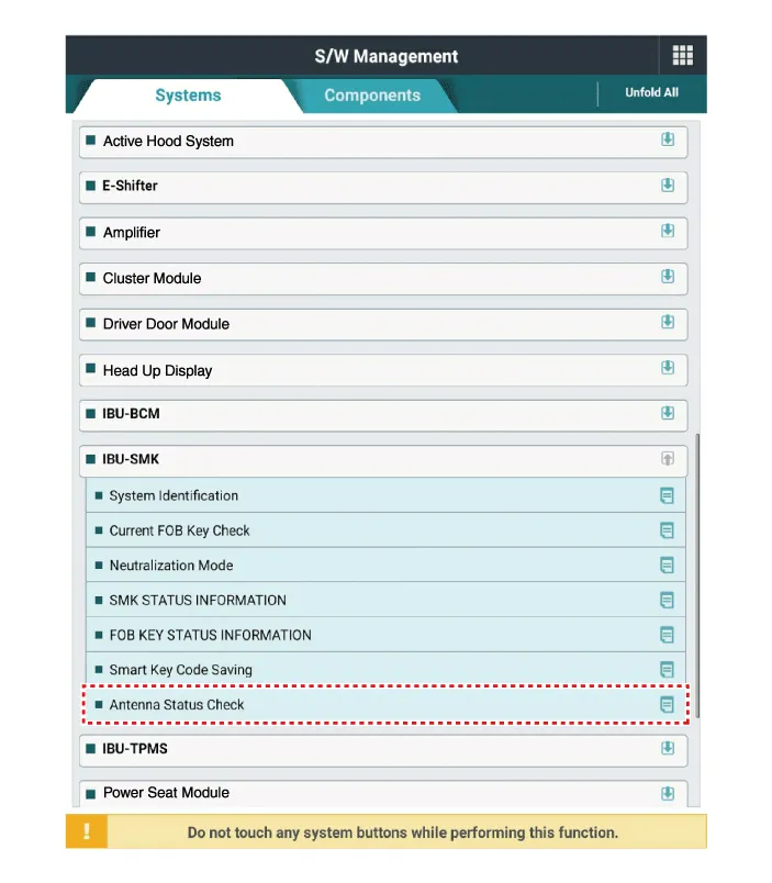
Antenna Status Check
| 1. |
Connect the cable of KDS to the data link connector in driver side crash pad lower panel. |
| 2. |
Select the "Antenna Status Check".
|

| 3. |
After IG ON, select the "Antenna Status Check".
|
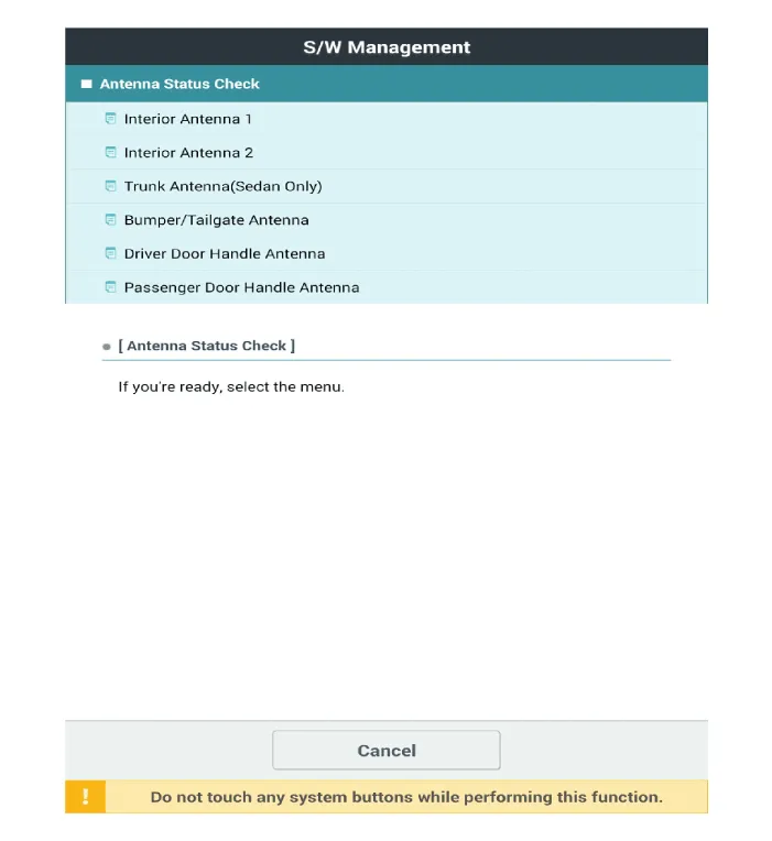
| 4. |
Set the smart key near the related antenna and operate it with a KDS.
|
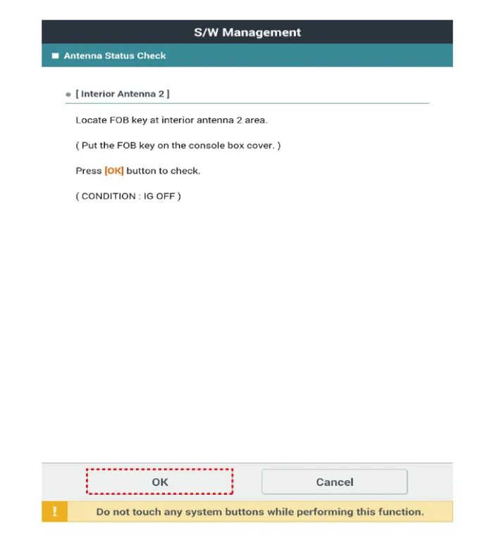
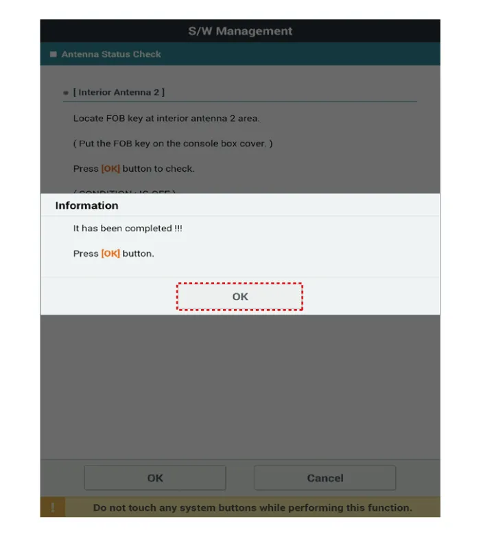
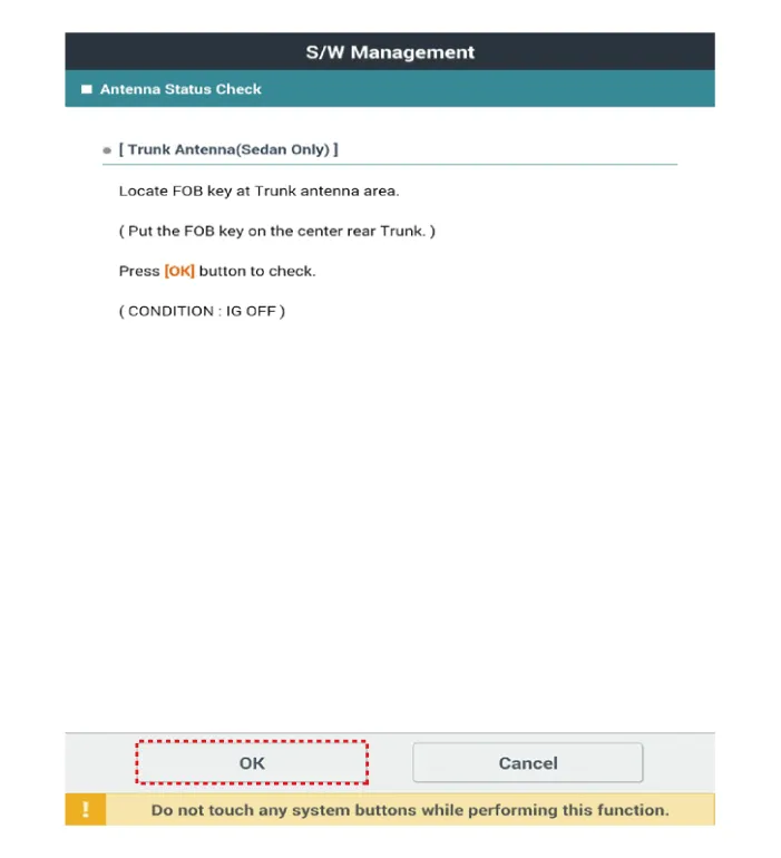

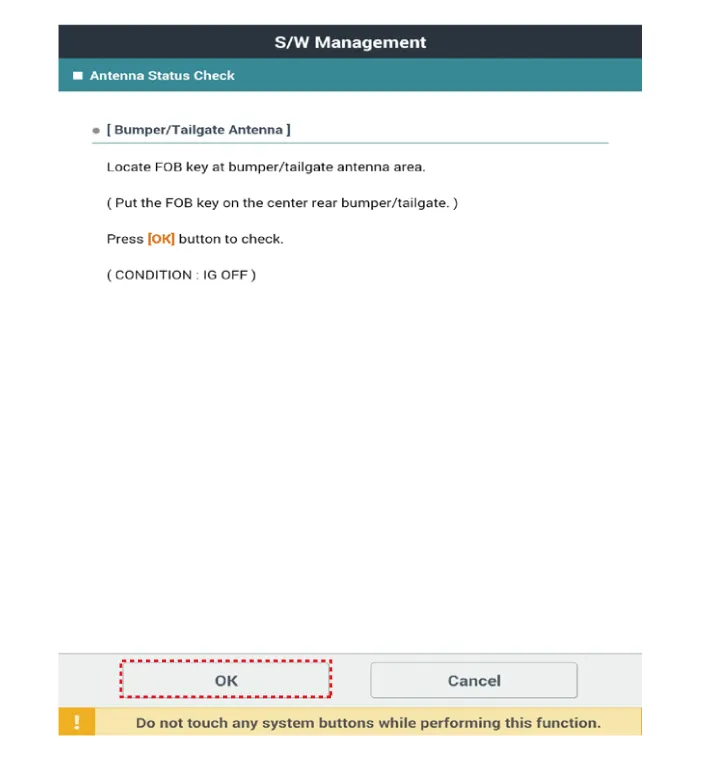
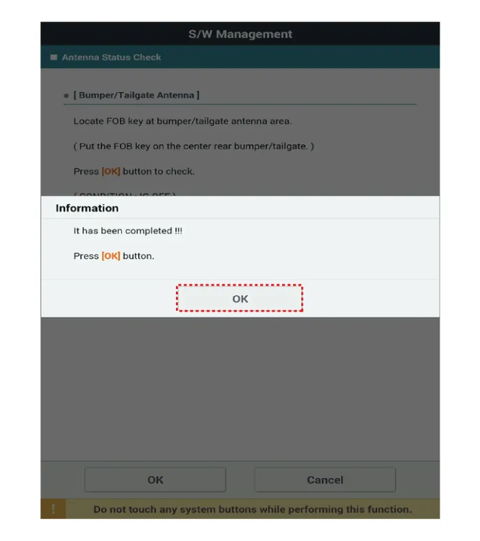
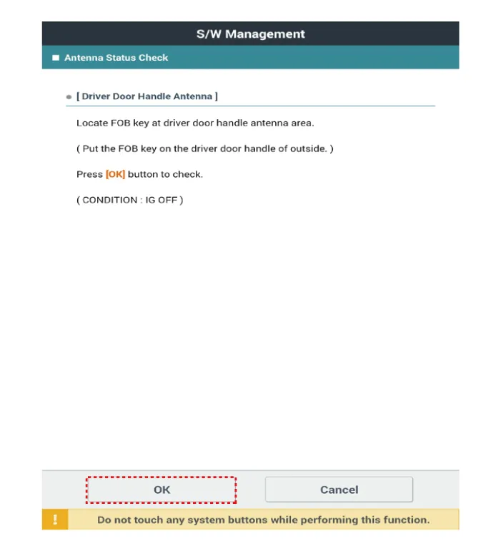
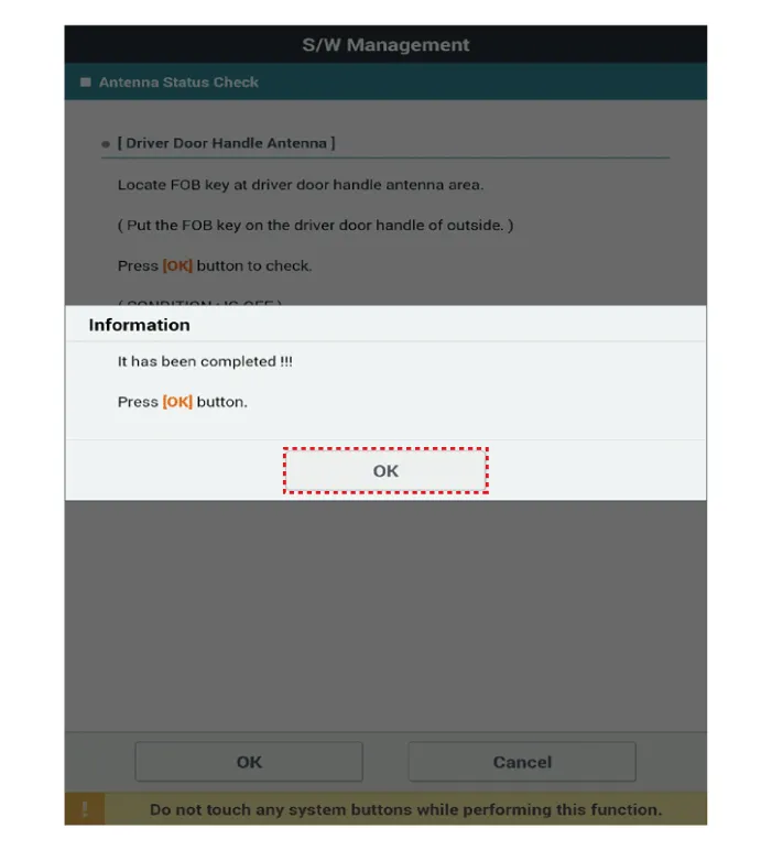
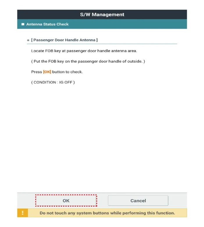
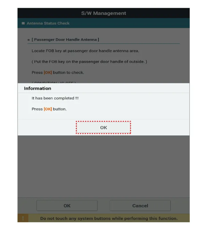
| 5. |
If the smart key runs normal , the related antenna, smart key(transmission, reception) and exterior receiver are normal. |
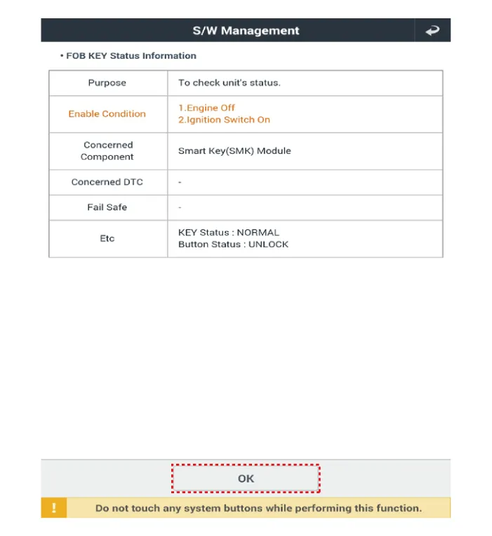
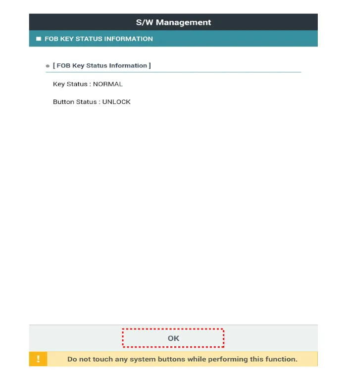
FOB Status Check
| 1. |
Connect the cable of KDS to the data link connector in driver side crash pad lower panel. |
| 2. |
After IG ON, select the "FOB KEY STATUS INFO".
|
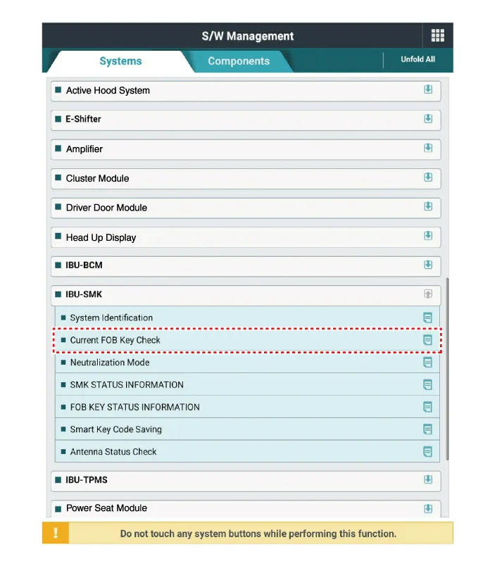
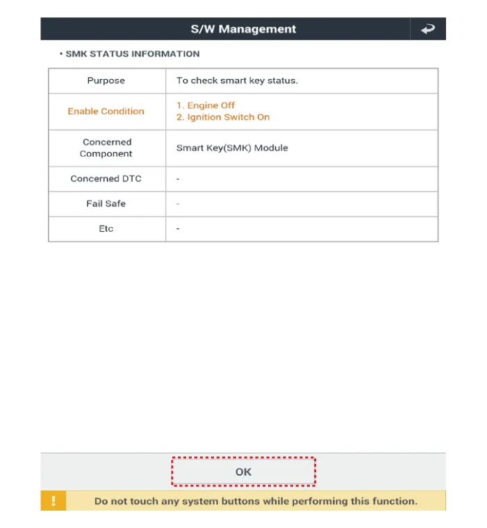
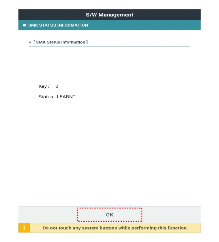
Smart Key Status Check
| 1. |
Connect the VCI dongle of the KDS to the data link connector in driver side crash pad lower panel. |
| 2. |
After IG ON, select the "SMK STATUS INFO".
|

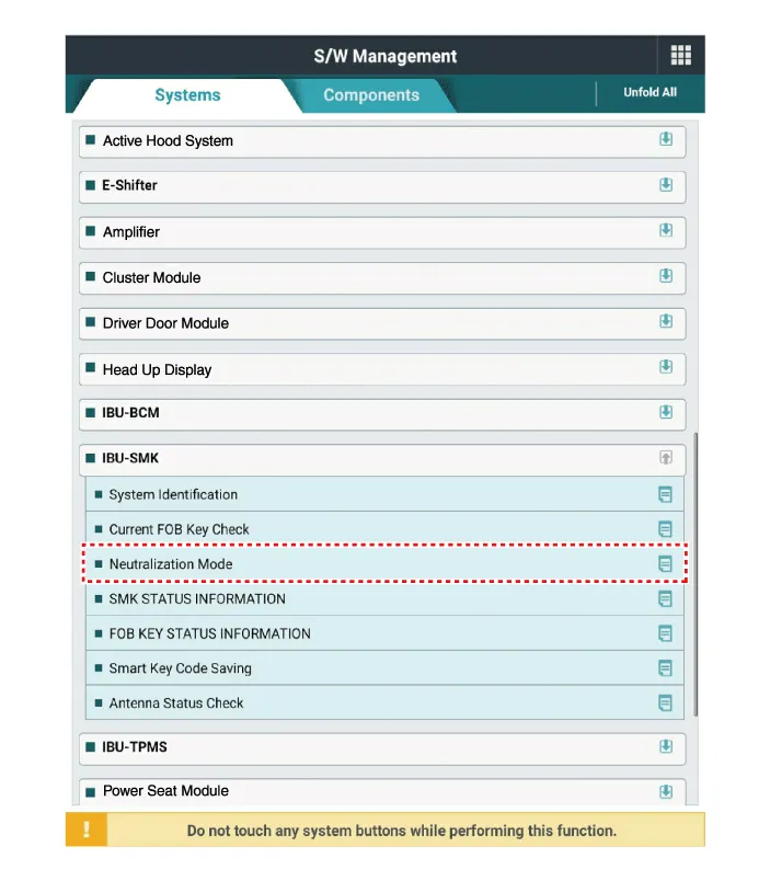
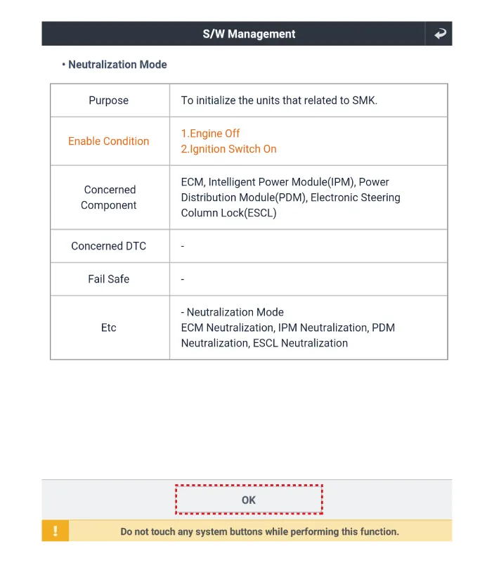
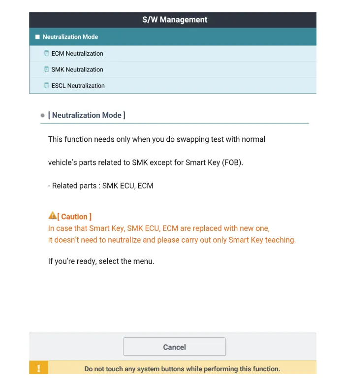
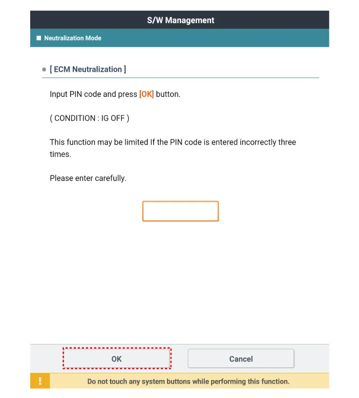
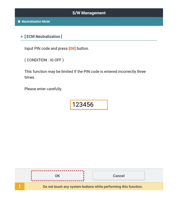
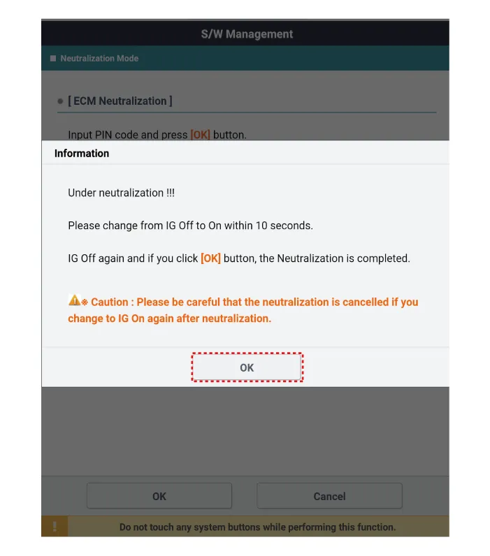
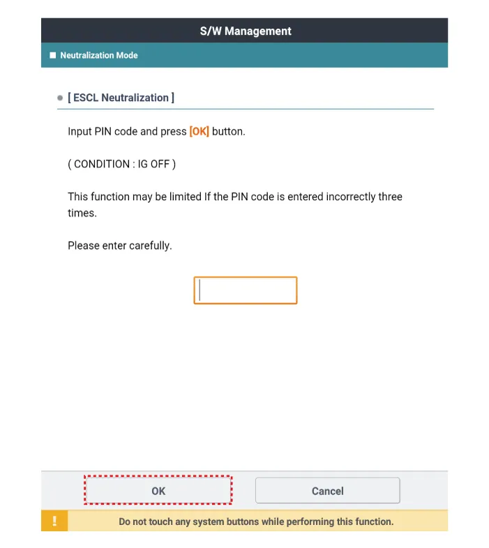
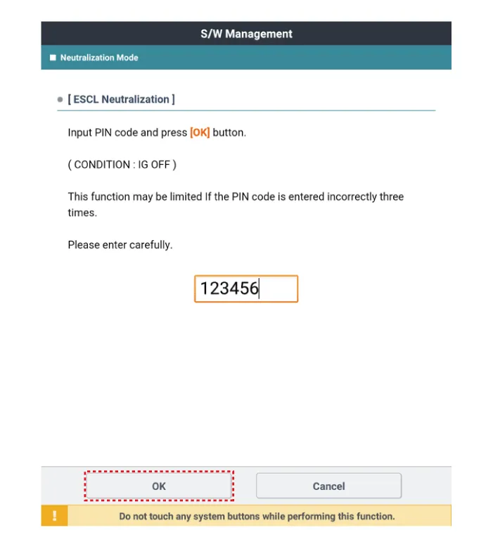
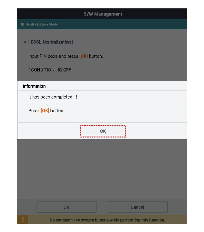
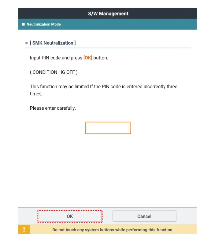
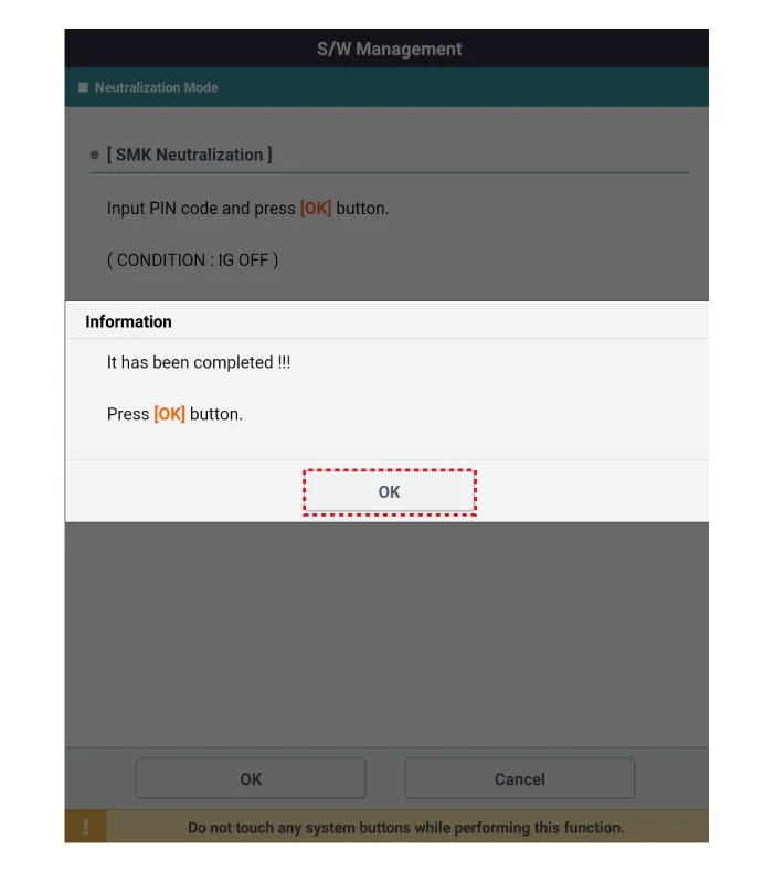
Neutralization Status Check
| 1. |
Connect the VCI dongle of the KDS to the data link connector in driver side crash pad lower panel. |
| 2. |
After IG ON, select the "Neutralization mode".
|

Repair procedures Removal Interior Antenna 1 1. Disconnect the negative battery terminal. 2. Remove the surround view monitor (SVM) unit.
Other information:
Kia Optima DL3 2019-2026 Service and Repair Manual: Room Lamp
Repair procedures Removal When removing with a flat-tip screwdriver or remover, wrap protective tape around the tools to prevent damage to components. 1.
Kia Optima DL3 2019-2026 Service and Repair Manual: Photo Sensor
Description and operation Description The photo sensor is located at the center of the defrost nozzles. The photo sensor contains a photovoltaic (sensitive to sunlight) diode. The solar radiation received by its light receiving portion, generates an electromotive force in proportion to the amount of radiation received which is
Categories
- Manuals Home
- Kia Optima Owners Manual
- Kia Optima Service Manual
- Brake System
- Body Electrical System
- Front Axle Assembly
- New on site
- Most important about car
