Kia Optima DL3: Body Side Molding / Side Sill Molding
Repair procedures
| Replacement |
Put on gloves to prevent hand injuries. |

|

| 1. |
Remove the front wheel guard. (Refer to Body Side Molding - "Front Wheel Guard") |
| 2. |
Remove the rear wheel guard. (Refer to Body Side Molding - "Rear Wheel Guard") |
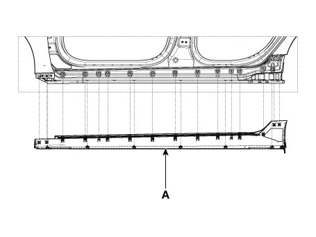
| 3. |
Using a remover and remove the side sill molding (A).
|
| 4. |
To install, reverse the removal procedure.
|

Repair procedures Replacement • Put on gloves to prevent hand injuries.
Repair procedures Replacement Put on gloves to protect your hands. • Use a plastic panel removal tool to remove interior trim pieces without marring the surface.
Other information:
Kia Optima DL3 2019-2026 Service and Repair Manual: Lighting System
Specifications Specification Item Tyep Watt (W) Front Headlamp A Type High beam LED - Low beam LED - Position/DRL LED -
Kia Optima DL3 2019-2026 Service and Repair Manual: Evaporator Temperature Sensor
Description and operation Description The evaporator temperature sensor will detect the evaporator core temperature and interrupt compressor relay power in order to prevent evaporator from freezing by excessive cooling. The evaporator temperature sensor has the Negative Temperature Coefficient (NTC).
Categories
- Manuals Home
- Kia Optima Owners Manual
- Kia Optima Service Manual
- Suspension System
- Headlamps
- Brake System
- New on site
- Most important about car
