Kia Optima DL3: Starting System / Starter Relay
Repair procedures
| Inspection |
| 1. |
Disconnect the negative battery (-) terminal. |
| 2. |
Remove the fuse box cover. |
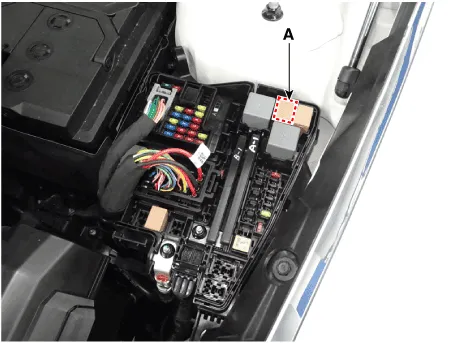
| 3. |
Remove the starter relay (A).
|
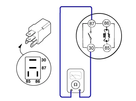
| 4. |
Check for continuity between the terminals (30 and 87) using an ohmmeter.
|
||||||||||
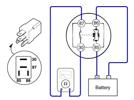
| 5. |
Apply 12V to the terminal 85 and ground to the terminal 86 and then check for continuity between the terminals (30 and 87).
|
||||||||||
| 6. |
Install the starter relay. |
| 7. |
Install the fuse box cover.26 |
Description and operation Description The starting system includes the battery, starter, solenoid switch, ignition switch, inhibitor switch (A/T), clutch pedal switch (M/T), ignition lock switch, connection wires and the battery cable.
Service data Specifications Purge Control Solenoid Valve (PCSV) ▷ Specification Item Specification Coil Resistance (Ω) 22.
Other information:
Kia Optima DL3 2019-2026 Service and Repair Manual: Rear Combination Lamp
Components and components location Component Location 1. Tail lamp 2. Stop lamp 3. Tail/Stop lamp 4. Back up lamp 5. Turn signal lamp Schematic diagrams Connector and Terminal Function [A Type] Pin Function Center Ou
Kia Optima DL3 2019-2026 Service and Repair Manual: Blower Unit
Components and components location Component Location 1. Blower unit assembly Components 1. Intake actuator 2. Cluster ionizer 3. Air filter 4. Blower motor assembly 5.
Categories
- Manuals Home
- Kia Optima Owners Manual
- Kia Optima Service Manual
- Lift And Support Points
- Steering System
- Body Electrical System
- New on site
- Most important about car
