Kia Optima DL3: Emission Control System
Service data
| Specifications |
Purge Control Solenoid Valve (PCSV)
▷ Specification
|
Item |
Specification |
|
Coil Resistance (Ω) |
22.0 - 26.0 [20°C (68°F)] |
Tightening torque
| Tightening Torques |
|
Item |
kgf.m |
N.m |
lb-ft |
|
Positive Crankcase Ventilation (PCV) Valve |
0.2 - 0.3 |
1.96 - 2.94 |
1.45 - 2.17 |
Description and operation
| Description |
Emissions Control System consists of three major systems.
| • |
Crankcase Emission Control System prevents blow-by gas from releasing into the atmosphere. This system recycles gas back into the intake manifold (Closed Crankcase Ventilation Type). |
| • |
Evaporative Emission Control System prevents evaporative gas from releasing into the atmosphere. This system burns gas at appropriate engine operating condition after gathering it in the canister. |
| • |
Exhaust Emission Control System converts the three pollutants [hydrocarbons (HC), carbon monoxide (CO), and oxides of nitrogen (NOx)] into harmless substances by using the 3-way catalytic converter. |
Troubleshooting
| Troubleshooting |
|
Symptom |
Suspect Area |
|
Engine will not start or stuggle to start |
Vapor hose damaged or disconnected |
|
Engine stuggle to start |
Malfunction of the Purge Control Solenoid Valve |
|
Rough idle or engine stalls |
Vapor hose damaged or disconnected |
|
Malfunction of the PCV valve |
|
|
Rough idle |
Malfunction of the Evaporative Emission Control System |
|
Excessive oil consumption |
Positive crankcase ventilation line clogged |
Schematic diagrams
| Schematic Diagram |
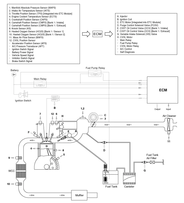
Components and components location
| Components Location |
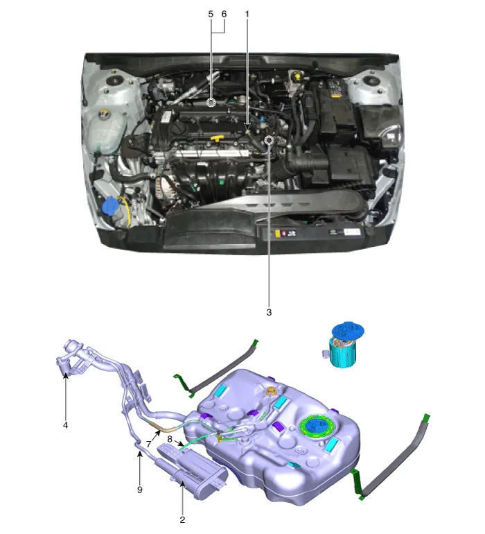
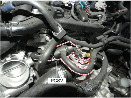
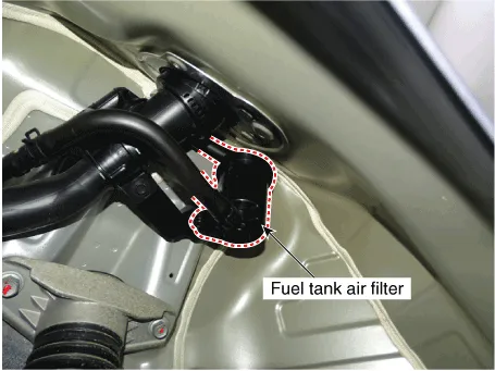
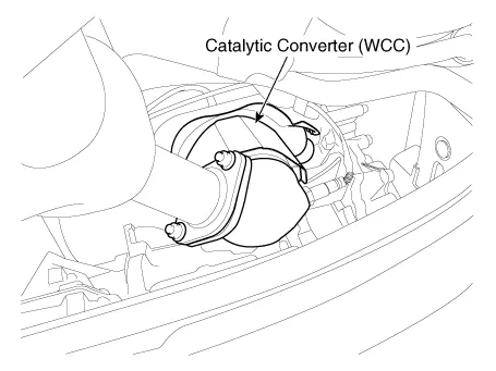
| 1. PCV valve 2. Canister 3. Purge control solenoid valve (PCSV) 4. Fuel Tank Air Filter 5. Catalytic converter (WCC) |
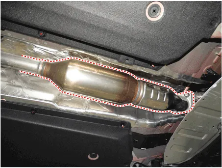
6. Catalytic converter (UCC)
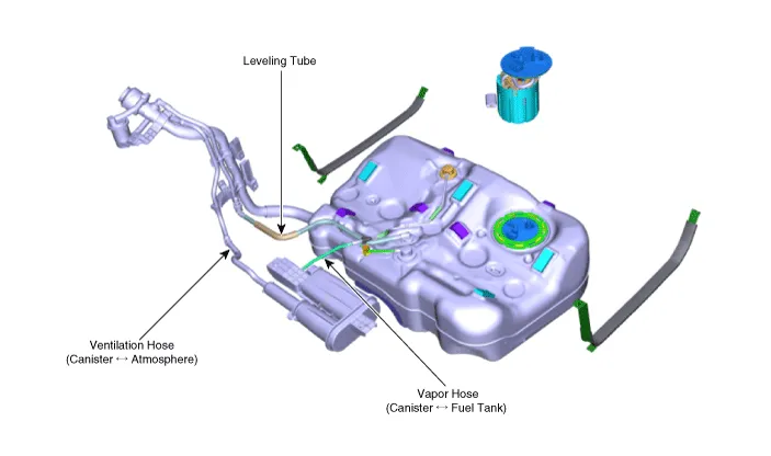
7. Leveling Tube 8. Vapor Hose (Canister ↔ Fuel Tank) 9. Ventilation Hose (Canister ↔ Atmosphere) |
|
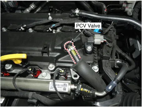
1. PCV valve |
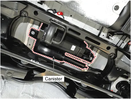
2. Canister |
|
|
|
|
3. Purge control solenoid valve (PCSV) |
4. Fuel Tank Air Filter |
|
|
|
|
5. Catalytic converter (WCC) |
6. Catalytic converter (UCC) |
|
|
|
|
7. Leveling Tube 8. Vapor Hose (Canister ↔ Fuel Tank) 9. Ventilation Hose (Canister ↔ Atmosphere) |
|
|
|
|
Repair procedures Inspection 1. Disconnect the negative battery (-) terminal. 2. Remove the fuse box cover.
Schematic diagrams Schematic Diagram Repair procedures Inspection 1. After disconnecting the vapor hose from the PCV valve, remove the PCV valve.
Other information:
Kia Optima DL3 2019-2026 Service and Repair Manual: Fog Lamp
Repair procedures Removal Front Fog Lamp 1. Disconnect the negative battery terminal. 2. Remove the front bumper assembly. (Refer to Body - "Front Bumper Assembly") 3.
Kia Optima DL3 2019-2026 Service and Repair Manual: Smart Key Unit
Schematic diagrams Connector and Terminal Function Pin Function Connector A Connector B Connector C Connector D 1 - Front washer switch (Output) - Driver outside handle switch (Input)
Categories
- Manuals Home
- Kia Optima Owners Manual
- Kia Optima Service Manual
- Steering System
- Rear Brake Disc
- Engine Mechanical System
- New on site
- Most important about car
