Kia Optima DL3: Timing System / Timing Chain Cover
Components and components location
| Components |
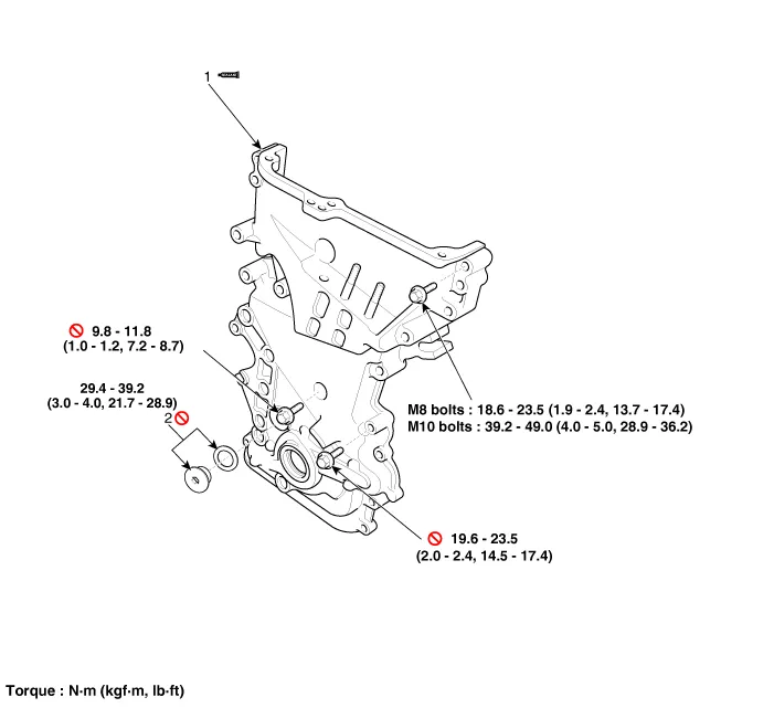
| 1. Timing chain cover |
2. Service plug bolt & gasket
|
Repair procedures
| Removal |
Engine removal is not required for this procedure.
|

Mark all wiring and hoses to avoid misconnection. |

| 1. |
Disconnect the battery negative terminal. |
| 2. |
Remove the RH front wheel. |
| 3. |
Remove the engine cover. (Refer to Engine and Transaxle Assembly - "Engine Cover") |
| 4. |
Remove the engine room under cover. (Refer to Engine and Transaxle Assembly - "Engine Room Under Cover") |
| 5. |
Remove the drive belt. (Refer to Drive Belt System - "Drive Belt") |
| 6. |
Remove the crankshaft damper pulley. (Refer to Drive Belt System - "Crankshaft Damper Pulley") |
| 7. |
Remove the water pump. (Refer to Cooling System - "Water Pump") |
| 8. |
Remove the drive belt tensioner. (Refer to Drive Belt System - "Drive Belt Tensioner") |
| 9. |
Remove the idler. (Refer to Drive Belt System - "Idler") |
| 10. |
Remove the alternator. (Refer to Engine Electrical System - "Alternator") |
| 11. |
Remove the A/C compressor. (Refer to Heating,Ventilation, Air Conditioning - "Compressor") |
| 12. |
Drain engine oil and remove the oil pan. (Refer to Lubrication system – “Oil Pan”) |
| 13. |
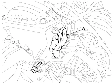
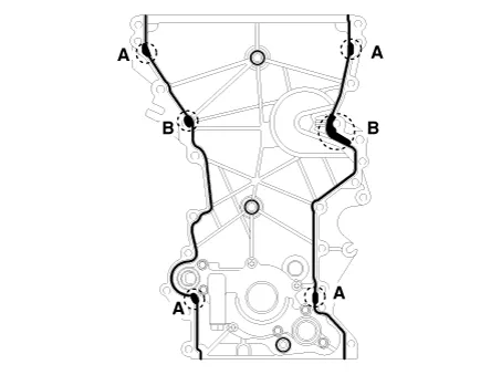
Remove the front engine hanger (A).
|
| 14. |
Remove the alternator. (Refer to Engine Electrical System - "Alternator") |
| 15. |
Remove the engine mounting bracket. (Refer to Engine and Transaxle Assembly - "Engine Mounting") |
| 16. |
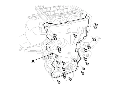
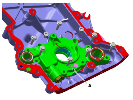
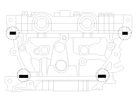
Remove the timing chain cover (A) by gently prying the gaps between the cylinder head and cylinder block.
|
| Installation |
| 1. |
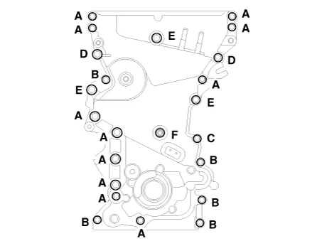
Install the timing chain cover.
|
| 2. |
Replace the front oil seal if necessary. (Refer to Timing System - “Front Oil Seal”) |
| 3. |
Install the front engine hanger (A).
|
| 4. |
Install the other parts reverse order of removal. |
| 5. |
Add all the necessary fluids and check for leaks. Connect KDS. Check for codes, note, and clear. Recheck.
|
Components and components location Components 1. Front oil seal Repair procedures Replacement 1.
Components and components location Components 1. Intake camshaft 2. Exhaust camshaft 3. Intake CVVT assembly 4.
Other information:
Kia Optima DL3 2019-2026 Service and Repair Manual: Integrated Memory Seat (IMS) Unit
Specifications Specifications Item Specifications Rated voltage DC 12 V Operating voltage DC 9 - 16 V Operating temperature range -22 to 167°F (-30 to 75°C) Dark current Max.
Kia Optima DL3 2019-2026 Service and Repair Manual: Panorama Sunroof
C
Categories
- Manuals Home
- Kia Optima Owners Manual
- Kia Optima Service Manual
- Charging System
- Motor Driven Power Steering
- Heating, Ventilation and Air Conditioning
- New on site
- Most important about car
